This thread has been locked.

If you have a related question, please click the "Ask a related question" button in the top right corner. The newly created question will be automatically linked to this question.

CC2652P: GPIO interrupt callback latency too long.

Part Number: CC2652P
Other Parts Discussed in Thread: SYSCONFIG

Hi, I use CC2652P, simplelink_cc13x2_26x2_sdk_4_40_04_04, CCS10.2

I tested latency between interrupt signal and irq callback using a key and a led.

The code is as below:

GPIO_setCallback(gpio_key1, gpio_key1_isr);
GPIO_enableInt(gpio_key1);

void gpio_key1_isr(uint8_t index)
{
    led_1_on();
}

The key signal waveform and led waveform is as below:

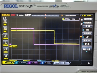
In the picture, the red waveform is key signal and the yellow waveform is led signal.

And we can see, there is a long latency about 70us between key signal and led signal, which means when a hardware signal changes, there will be a 70us latency before the irq callback runs.

How can I minimal this latency please? 70us is really too long. 

  • This might be the real latency on TI RTOS interrupt/callback. Can you elaborate what application you mean to achieve? Maybe there’s alternative to do it.

  • Hi yingtao,

    Which example are you referencing?  Is this a consistent delay or does it vary?  Does you device enter idle or standby modes?  You could try to bypass the TI Drivers Runtime APIs GPIO.h by directly controlling the TI Driverlib gpio.h/ioc.h/interrupt.h to reduce latency.

    Regards,
    Ryan

  • I'm referencing the example as below:

    I tested several times, and it's a consistent delay.

    I'm not pretty sure whether the device is in standby mode or idle mode.

    I think you can easily observe this phenomenon by a similar test as I did.

    In my application, I need to response to an outside interrupt signal as soon as possible. The latency should preferably be less than 1us if possible.

    I'm studying the TI Driverlib gpio.h/ioc.h/interrupt.h, and trying hard to test to achieve the minimal latency.

    I would appreciate that if you can also provide me some example code to demonstrate how to directly control the TI Driverlib.

  • An IEEE 802.15.4 2.4 GHz sensor is designed to enter standby mode if it is not communicating on the network, therefore this will increase the wakeup time to service the interrupt.  You can view the GPIO TI Driver in source\ti\drivers\gpio to determine how it interacts directly with Driverlib, however there are no default examples provided for this layer.  Perhaps you can find a similar use case by searching online. 

    Regards,
    Ryan

  • Thanks. In this IEEE 802.15.4 2.4 GHz sensor example, can I stop the device from entering standby mode for a while? For example, are there APIs I can use in my application to disable standby mode and enable standby mode? 

  • You would need to modify the application's handling of the corresponding API MAC attribute, ApiMac_mlmeSetReqBool(ApiMac_attribute_RxOnWhenIdle, CONFIG_RX_ON_IDLE); where CONFIG_RX_ON_IDLE is false for sleepy devices and true for non-sleepy.  CONFIG_RX_ON_IDLE is set inside the SysConfig file's RF STACKS -> TI 15.4-Stack -> Power module and you must take caution to how it is evaluated in both the jdllc.c and sensor.c files.

    Regards,
    Ryan