This thread has been locked.

If you have a related question, please click the "Ask a related question" button in the top right corner. The newly created question will be automatically linked to this question.

CC2538: OTA server PC Tool

Part Number: CC2538
Other Parts Discussed in Thread: Z-STACK, SEGGER, , CC2530

Hello Guys,

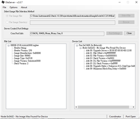
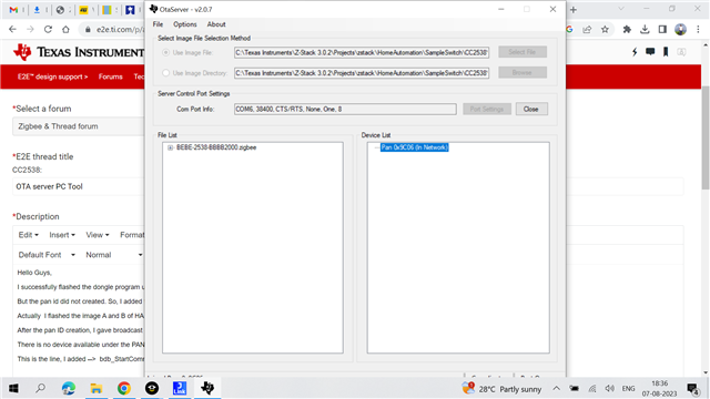
I successfully flashed the dongle program using the option (Download and Debug) , Then I opened OTA server PC Tool. In that, I gave all the parameters and select open port.

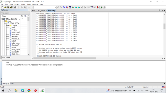
But the pan id did not created. So, I added the B2B line in the end of OTA_Dongle_Init. Atlast, the pan ID created successfully.

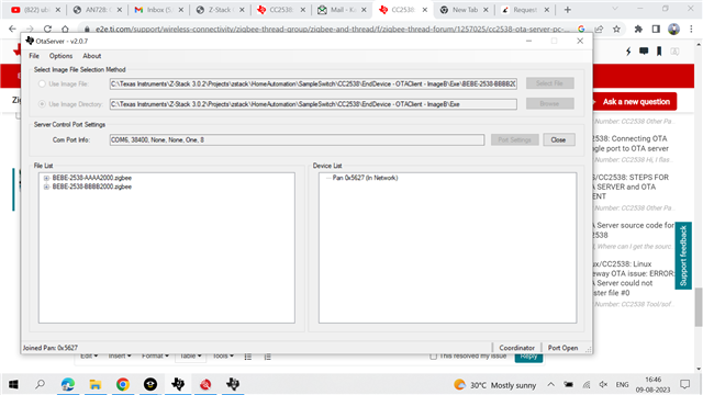
Actually  I flashed the image A and B of HA sampleswitch application.

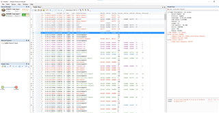
After the pan ID creation, I gave broadcast image notify option in device list. I enclosed the image whatever it shows in given below.

There is no device available under the PAN ID.

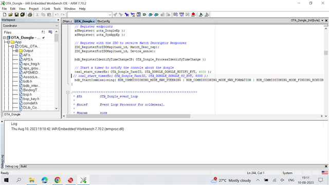
This is the line, I added -->  bdb_StartCommissioning(BDB_COMMISSIONING_MODE_NWK_FORMATION | BDB_COMMISSIONING_MODE_NWK_STEERING);

I don't how to go to the next step.

I am using z-stack - 3.0.2 and EWARM - 9.40.1.

Best Regards,

Kamalesh.C

  • I would suggest you to use sniffer to check the whole process to know what exactly happened.

  • Ok. But In packet sniffer, how to proceed further. Actually, I am new to this packet sniffer. What type of document I have to give ?

    Where the packet sniffered documents are there ? Or Is there any related document or link is appreciated.

    Best Regards,

    Kamalesh.C

  • Hello Kamalesh,

    The OtaServer tool appears to be communicating with your OTA_Dongle project, which has formed a Zigbee network.  The general convention is that you have 180 seconds (BDBC_MIN_COMMISSIONING_TIME defined in bdb_interface.h) for an OTA-enabled HA SampleSwitch Application (End Device and Router build options available) to join the network.  This is covered in Sections 3.2.2 and 3.3 of the Z-Stack 3.0.2\Documents\Z-Stack OTA Upgrade User's Guide.pdf resource.  As YK suggested, getting a Packet Sniffer setup is still an excellent idea so that you can continue to develop and explore this application use case.

    Regards,
    Ryan

  • Hello Guys,

    I installed Ubiqua analyzer. I created the custom adapter for images(board-1). But, there is nothing detected. Is there any settings to be open ?.

    I enclosed the image of this analyzer given below. What I will do ?

    Best Regards,

    Kamalesh.C

  • Process for these OTA.

    1) Download the Image- A with bootloader to the client board with jlink segger and also the build the image B to create the zigbee file whichever upload for the ota serverpctool(updated zigbee image).

    2) Download the dongle image to the server board  with jlink segger.

    3) Open the application which is OtaServer PC tool and made the setup of port for dongle board (server) and the pan id is created successfully. But the node ID is not created.

    4) Is this process is correct or not ? I want to know whether any step I missed or not ? Could you please tell me ?

    Best Regards,

    Kamalesh.C

  • Make sure you sniff the same channel used by your OTA network.

  • Are you using Channel 26 in your dongle and OTA client applications?  You should at least see a Link Status message from the ZC every 15 seconds.  Keep in mind that the sniffer tool should be neither OTA communication device (i.e. tertiary device).

    Your process is essentially correct, however there are specific details which much be further addressed once you have confirmed that the OTA client is able to join the dongle's established network.

    Regards,
    Ryan

  • How to make a setup of dongle to channel - 26 and client also ? I don't know about the sniffer tool also. Could you please tell me the procedure ?

    Best Regards,

    Kamalesh.C

  • How to check the channel number of dongle program and client program (Sample Switch) ?

    What are all the other steps to get the sniffer from the board(client) ?

    Adding client functionality to the client board is required for this ? Why because I didn't add anything to this board. Is required for this Sample Switch ?

    Best Regards,

    Kamalesh. C

  • If you are not sure which channel you use, you can scan all 16 channels one-by-one with your Ubiqua Protocol Analyzer to check which channel contains the PANID shown on your OTA Server GUI.

  • Hi chen,

    I checked all the 16 channels, In all the channels the traffic bar of ubiqua analyzer is in empty state. No other PANID is displayed in the sniffer tool.

  • I have to add the client functionality in the client board or It is already added in the Sample Switch program.

  • SampleSwitch project already contains OTA client. Please refer to Z-Stack OTA Upgrade User's Guide.pdf

  • Ok. Then, What is the problem behind this sniffer ota ? It didn't give the PANID ?

  • What do you mean "It didn't give the PANID?" Do you refer to Z-Stack OTA Upgrade User's Guide.pdf and follow the steps inside?

  • Sorry, I did all the steps whatever in that document(Z-stack). But, In that Sniffer scanned all the 16 channels. PANID didn't generated during the scanning process. 

  • Can you do a screenshot to show me what you see on your current OTA server GUI? Does it show PANID?

  • Yes sure.

    It shown the PANID, FIrst of all I added the bdb line in the program of dongle in the part of  Ota_Dongle_Init, Then only the PANID appeared.

    Actually my board having the user button or reset button, when I press the button PANID disappeared and appeared again.

    I enclosed the picture of my OTA SERVER PC TOOL below.

    Best Regards,

    Kamalesh.C

  • Ideally you would first evaluate with TI EVMs and the default OTA examples to further understand the design.  The OTA client switch examples also have UI available to confirm whether they have joined the OTA dongle's Zigbee network.  Are you using the same device and stack version for the joining client application?  DEFAULT_CHANLIST is determined in the Tools/f8wConfig.cfg of both projects and is relatively easy to set only one specific channel to be used.

    Regards,
    Ryan

  • Hi Ryan Brown,

    We are using our custom board using CC5238 microcontroller, I want to do OTA with our board. By our board only, We did these all process till the PANID creation.

    Can I do OTA with our carrier board? What are all the specification required for this OTA in our carrier board ?

    Do you want any information about our carrier board means feel free to ask ?

    I want to create the node and transfer the image between dongle and client board.

    Best Regards,

    Kamalesh.C 

  • You can do OTA with custom boards and OtaServer.  Have you tried your carrier board with other ZC application examples?  The Device List confirms that the OTA Dongle has created a Pan ID (0x5627) which means it has started the Zigbee Network.  You can pre-determine the PANID inside of f8wConfig.cfg as well to confirm

    Regards,
    Ryan

  • Hi Ryan,

    What is meant by pre-determine the PANID ? I have to include in that  PANID in that configuration file?

    But, I didn't try other applications. Other application means sampleLight, SampleDoorLock like these ?

    Best Regards,

    Kamalesh.C

  • /* Define the default PAN ID.
     *
     * Setting this to a value other than 0xFFFF causes
     * ZDO_COORD to use this value as its PAN ID and
     * Routers and end devices to join PAN with this ID
     */
    -DZDAPP_CONFIG_PAN_ID=0xFFFF

    Yes, SampleLight and SampleDoorLock are examples of other ZC-capable applications.

    Regards,
    Ryan

  • I would like to suggest you to set -DDEFAULT_CHANLIST=0x00002000 in f8wconfig.cfg to use channel 13 on OTA dongle so we can sniff channel 13 directly.

  • Ok guys, I will try and get back to you soon.

    Best Regards,

    Kamalesh.C

  • I tried the PANID setup in OTA DONGLE program and rebuild all, then I did the debug and downloading in dongle board. After these disconnect the j-link debugger and stop debugging. Check with the OtaServer pc tool, PANID is changed as different and same previous condition which is there is no node creation.

    Is there any mistakes in my previous processes ?

    In which I want to change the -DDEFAULT_CHANLIST ?

    Best Regards,

    Kamalesh.C

  • I did the channel setup also, But there is no response in Ubiqua analyser.

    Can I add a device (node) under PANID, How to add ? This will work?

    Add a device option asked for short address and endpoint ? Where are those two option from the program ?

    Best Regards,

    Kamalesh.C 

  • A node will only be added to OtaServer once a device joins the OTA dongle network.  Have you updated the ZED/ZR SampleSwitch OTA client firmware for the correct channel as well, and do you enable BDB steering (as part of commissioning to join an open network) on this device?  If you are struggling with Ubiqua then perhaps you will have greater success with Packet Sniffer 2 and Wireshark.

    Regards,
    Ryan

  • Hi Ryan,

    What do you mean by ZED/ZR SampleSwitch update ? and WIreshark will work on these OTA ?

    I enclosed some images regarding that sniffer and I added some configuration in programs.

    This is addition of bdb steering.

    This is made a setup of PANID and channel - 25, I referred this setting from your one of the forum.

    These are the configuration, You want any information, ask me ?

    Best Regards,

    Kamalesh.C

  • The device which is joining the OTA dongle network must also have the same channel configuration.  I assume the SampleSwitch is being used since it was referenced earlier.  Wireshark can sniff Zigbee packets and the instructions are provided in the E2E link that YK provided.

    Regards,
    Ryan

  • For your reference, I do the following step to test OTA server/client and I can see it run without problem on my CC2538DK.

    1. Set both BDB_DEFAULT_PRIMARY_CHANNEL_SET and BDB_DEFAULT_SECONDARY_CHANNEL_SET as 0x00002000 in bdb_interface.h of OTADongle (Coordinator) project to force it uses channel 13.

    2.Add "bdb_StartCommissioning(BDB_COMMISSIONING_MODE_NWK_FORMATION | BDB_COMMISSIONING_MODE_NWK_STEERING);" in the end of OTA_Dongle_Init(OTA_Dongle.c) to make OTA dongle would start itself after reset every time.

    3.Start commission on SampleSwitch running on another CC2538 or CC2530 to join OTA dongle and I can see packet exchange in my Ubiqua and see SampleSwitch add in OTA server GUI.

     '

  • Hi,

    I downloaded both image and dongle program using j-link debugger. When I opened the OtaServer PC tool, connect both cc2538 custom board (without debugger) to the same PC. Then give the configuration of port settings(dongle port) and select the image. Click the option(open) and the PANID created, but the node did not created.

    This process is correct or not?

    In document, They are all say about the SampleApp to build. Is this is required ?

    I did only the SampleSwitch application part, That's why I asking ?

    I did the settings whatever Yikai chen said, But no reponse in ubiqua analyser.

    Best Regards,

    Kamalesh.C

  • Please refer to Chapter 3. Using the Sample OTA Applications in Z-Stack OTA Upgrade User's Guide.pdf to build and run SampleSwitch  on your another CC2538 to join OTA server. Then, you can see communication in your Ubiqua. By the way, the default SampleSwitch is design to run on TI CC2538DK with LCD/BTN on it and you might need to revise application code by yourself for your CC2538 custom board.

  • Hi chen,

    SampleSwitch program is only for TI CC2538DK ? or For our carrier board, Is there any general OTA application in z-stack application ?

    In our carrier board also have the button, Using that button only reset the PANID. This button will work for that SampleSwitch application. Modification means how to modify ?

     Best Regards,

    Kamalesh.C

  • Basically, yes, SampleSwitch is major for TI CC2538DK/CC2530DK which has LCD/BTNs on it. If you have your own custom board, you have to revise SampleSwitch according to your schematics by yourself.

  • Actually, I have a doubt which is my ultimate aim , we are using contiki os in our board. We have some sensors, each and every sensors have some different programs with respect to contiki os. I want to include the sensors program into this OTA. Is this is possible ?

    Is there any related link or forum is there for this process ?

    Could you please share any related documents over here ?

    Best Regards,

    Kamalesh.C

  • Do you mean to run Contiki or Zigbee on CC2538?

  • I have contiki os and In that contiki os, we created program for sensors whatever in our board as per the contiki os. In our board have zigbee network, I want to do the sensor programming through the ota between our boards.

    Is it possible ?

    If you want any information regarding our carrier board, feel free to ask ?

    Best Regards,

    Kamalesh.C

  • Because, In our board have CC2538 microcontroller, that's why zigbee network is there.

  • For you case, I suggest you to use CC2538/CC26x0/CC26x2 Serial Bootloader Interface to update your application on CC2538.

  • Why did you suggest this document ? Is there relation between my application and this document ?

    Actually I have so many application program by sensors and actuators as well. I want to update the program through air(for example, temperature sensor program is running currently means I want to change the pressure sensor program by air) This is my required process. That's Why I came to this OTA. 

    Serial Bootloader Interface fulfill my required application ?

    Best Regards,

    Kamalesh.C

  • You describe you have another carrier board running Zigbee network and CC2538 running Contiki with sensor related code. I suppose you have another host MCU on your carrier board to run Zigbee network stuff, right? If so, you can use your host MCU connecting with CC2538 serial bootloader to update Contiki sensor related code. If I misunderstand anything, please elaborate your case to me.

  • Actually, we have only one carrier board which is having CC2538 microcontroller, If this microcontroller have the zigbee network. Using this carrier board, I want to setup two cases:

    1) one carrier board (CC2538) as Dongle --> to create a network.

    2) one carrier board (CC2538) as client --> I want to change another program ( sensor program).

    Carrier Board - This board only having CC2538 (this is customized for IOT) which is o-mote(This is the name of our board, We are also available in online also). I want to do program update( My client boarding executing LED BLINKING program means I want to change as BUTTON PROGRAM)

    Is it possible ?

    Best Regards,

    Kamalesh.C

  • If your CC2538 run Z-Stack application, you can do Zigbee OTA to update the firmware on it and the steps are described in Z-Stack OTA Upgrade User's Guide.pdf

  • In these case, firmware means the application program (like led_blinking, button programming) right ?

    I want to add the client functionality in application program which is sensor program of mine ? or how to do these OTA process with my sensor is in contiki program format ? This will work?

    Best Regards,

    Kamalesh.C

  • Yes, firmware means the application program and of course you can add the client functionality in application program which is sensor program of yours. For OTA process, what do you mean contiki program format. If you use Zigbee OTA, you must run Z-Stack application and it won't be Contiki format.

  • z-stack application means I want to convert the contiki format to z-stack format right ?

    I give the format of contiki below for hello world program.

    #include "contiki.h"

    #include <stdio.h> /* For printf() */
    /*---------------------------------------------------------------------------*/
    PROCESS(hello_world_process, "Hello world process");
    AUTOSTART_PROCESSES(&hello_world_process);
    /*---------------------------------------------------------------------------*/
    PROCESS_THREAD(hello_world_process, ev, data)
    {
      PROCESS_BEGIN();

      printf("Hello, world\n");

      PROCESS_END();
    }

    I included multithreading concept in this program.

    What I have to do ?

    Best Regards,

    Kamalesh.C

  • Contiki is a RTOS system but CC2538 Z-Stack isn't. I don't know how you can convert the contiki format to z-stack format...

  • Adding client functionality means without changing the content of the program, we have to add some packages related to OTA with that programming file. right?

    We don't need to change the program. right?

    We have to create the folder which is .c file and OTA dependencies (Adding client functionality) to send through OTA.

    Above statements are all right ? Actually I am totally confused ? Could you please share any related details according to these.

    Best Regards,

    Kamalesh.C