This thread has been locked.
If you have a related question, please click the "Ask a related question" button in the top right corner. The newly created question will be automatically linked to this question.
Hai,
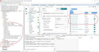
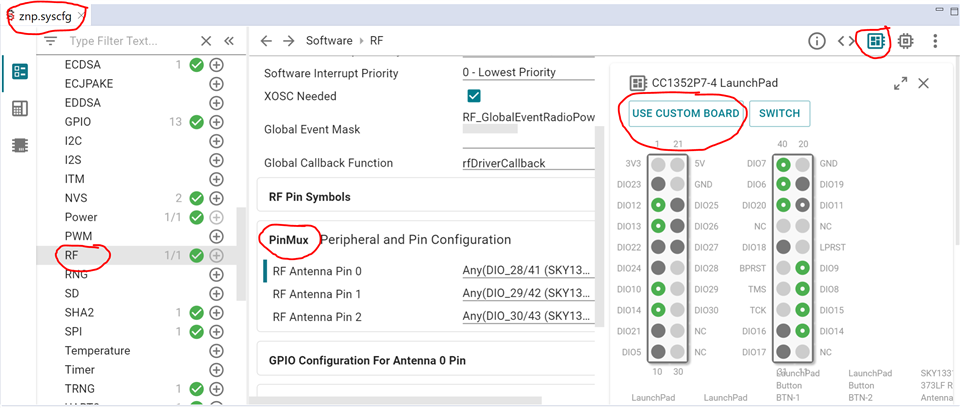
I'm trying to Build Zigbee Network Processor (ZNP) Example for CC2652P7 chip.
I want to use 20 dBm output power.
Which Launchpad I need to select?
How to set Target?
any other configuration need to do?
Best Regards
Bose
Hi Bose,
The Z-Stack Migration Guides notes that you can use the LAUNCHXL-CC1352P7 examples as the baseline for the CC2652P7 build, however the (-1) variant only supports non-PA operation of up to +5 dBm whereas (-4) supports PA for up to +10 dBm at 2.4 GHz. As such, here are the steps required to build a project for +20 dBm:
{-20, RF_TxPowerTable_DEFAULT_PA_ENTRY(6, 3, 0, 2) }, // 0x04C6 {-18, RF_TxPowerTable_DEFAULT_PA_ENTRY(8, 3, 0, 3) }, // 0x06C8 {-15, RF_TxPowerTable_DEFAULT_PA_ENTRY(10, 3, 0, 3) }, // 0x06CA {-12, RF_TxPowerTable_DEFAULT_PA_ENTRY(12, 3, 0, 5) }, // 0x0ACC {-10, RF_TxPowerTable_DEFAULT_PA_ENTRY(15, 3, 0, 5) }, // 0x0ACF {-9, RF_TxPowerTable_DEFAULT_PA_ENTRY(16, 3, 0, 5) }, // 0x0AD0 {-6, RF_TxPowerTable_DEFAULT_PA_ENTRY(20, 3, 0, 8) }, // 0x10D4 {-5, RF_TxPowerTable_DEFAULT_PA_ENTRY(22, 3, 0, 9) }, // 0x12D6 {-3, RF_TxPowerTable_DEFAULT_PA_ENTRY(19, 2, 0, 12) }, // 0x1893 {0, RF_TxPowerTable_DEFAULT_PA_ENTRY(19, 1, 0, 20) }, // 0x2853 {1, RF_TxPowerTable_DEFAULT_PA_ENTRY(22, 1, 0, 20) }, // 0x2856 {2, RF_TxPowerTable_DEFAULT_PA_ENTRY(25, 1, 0, 25) }, // 0x3259 {3, RF_TxPowerTable_DEFAULT_PA_ENTRY(29, 1, 0, 28) }, // 0x385D {4, RF_TxPowerTable_DEFAULT_PA_ENTRY(35, 1, 0, 39) }, // 0x4E63 {5, RF_TxPowerTable_DEFAULT_PA_ENTRY(23, 0, 0, 57) }, // 0x7217 {14, RF_TxPowerTable_HIGH_PA_ENTRY(22, 3, 1, 19, 27) }, // 0x1B27D6 {15, RF_TxPowerTable_HIGH_PA_ENTRY(26, 3, 1, 23, 27) }, // 0x1B2FDA {16, RF_TxPowerTable_HIGH_PA_ENTRY(30, 3, 1, 28, 27) }, // 0x1B39DE {17, RF_TxPowerTable_HIGH_PA_ENTRY(37, 3, 1, 39, 27) }, // 0x1B4FE5 {18, RF_TxPowerTable_HIGH_PA_ENTRY(32, 3, 1, 35, 48) }, // 0x3047E0 {19, RF_TxPowerTable_HIGH_PA_ENTRY(34, 3, 1, 48, 63) }, // 0x3F61E2 {20, RF_TxPowerTable_HIGH_PA_ENTRY(53, 3, 1, 58, 63) }, // 0x3F75F5 RF_TxPowerTable_TERMINATION_ENTRY
Let me know if these instructions are suitable for your needs.
Regards,
Ryan
Hai Ryan,
I Followed your instruction & Successfully Compiled the code.
In our Custom board design, we found RF Antenna switch pin (PA) got swapped.
Now I want to change DIO28 to DIO29 and DIO29 to DIO28.
How to change in software?
I tried to change in .syscfg but RF_antenna_pin0 is aligned to DIO28 & RF_antenna_pin1 is aligned to DIO29.
I can't change there pins.
How can I assign RF_antenna_pin0 to DIO29 & RF_antenna_pin1 is aligned to DIO28.
Regards
Bose
Once you select "USE CUSTOM BOARD" from the SysConfig Board View then you will be able to modify these pins from the RF Module's PinMux window.
You can also refer to the Custom Hardware section of the Z-Stack User's Guide.
Regards,
Ryan