Other Parts Discussed in Thread: CC2650, TIDA-00650
Hi, I'm working with the CC2650 SensorTag.
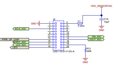
I want to develop an expansion board with a thermocouple connector and I'm following the guidelines given here for the reference design board (TIDA-00650) :
http://www.ti.com/tool/TIDA-00650
(Wireless Thermocouple Sensor Transmitter DevPack for SensorTag Reference Design).
I have a doubt about the connections in the schematic on the TIDA-00650.
As you can see the ADC on the expansion board (TIDA-00650) receives the clock signal of the SPI interface from the sensor tag (CC2650) through pin 5 of the on-board 20-pin connector.
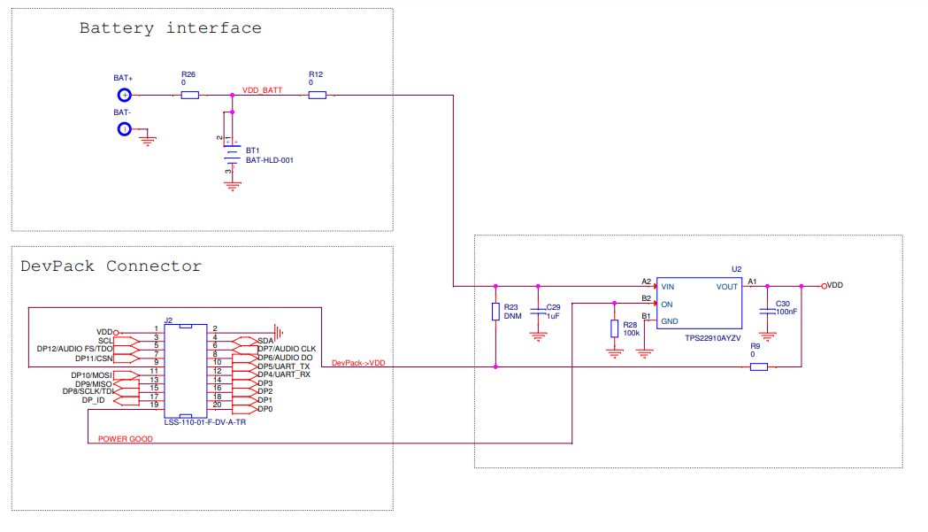
The respective connector on the CC2650 Sensor Tag is showcased in the schematic here:
(http://www.ti.com/lit/df/swrr134c/swrr134c.pdf)
It's basically the same connector positioned in a mirrored way. So pin5 of the connector on the expansion board will end up being connected to pin 6 of the connector on the CC2650.
This pin on the CC2650 is labeled as DP7/Audio CLK.
My doubt is that the clock of the SPI bus should be passed to the expansion board through pin DP8/SCLK/TDI of the CC2650 connector, that is pin number 15.
That means, due to the mirrored connections, that the SCLK_ADC signal on the TIDA-00650 schematic should be taken from pin16 and NOT from pin5.
Is this a mistake in the TIDA-00650 reference board or am I missing something? Maybe Audio_CLK can be used as an SPI clock signal as well through ad hoc software programming on the CC2650?
Thank you for your support!


