I have wireless PIR(433 Mhz) with remote control encoder SC2262. In datasheet written:
A Code Bit is the basic component of the encoded waveform, and can be classified as either an AD
(Address/Data) Bit or a SYNC (Synchronous) Bit.
Address/Data (AD) Bit Waveform.
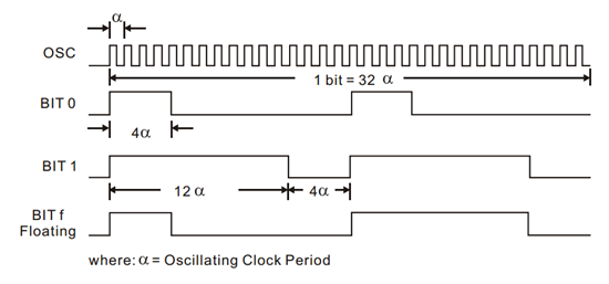
An AD Bit can be designated as Bit “0”, “1” or “f” if it is in low, high or floating state respectively. One bit
waveform consists of 2 pulse cycles. Each pulse cycle has 16 oscillating time periods. For further
details, please refer to the diagram below:
Synchronous (Sync.) Bit Waveform.
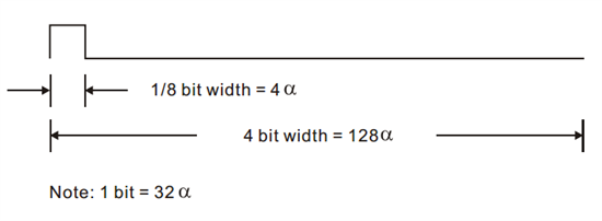
The Synchronous Bit Waveform is 4 bits long with 1/8 bit width pulse. Please refer to the diagram below:
A group of Code Bits is called a Code Word. A Code Word consists of 12 AD bits followed by one Sync Bit.
A Code Frame consists of four (4) continuous Code Words.
What I do:
Oscillator frequency of SC2262 is 10KHz. So Oscillating Clock Period(alpha) = 100Us.
4*alpha=400Us, so if i do data rate on cc1101 = 2500 baud, he must receive
AD BIT 0 as 10001000
AD BIT 1 as 11101110
AD BIT f as 10001000
Synchronous Bit as 10000000000000000000000000000000
AD bits set by tri-state jumpers. I have no jumpers, and my AD bits are ffffffffffff.
And I expect receive on cc1101 this frame:((AD BIT f)*12 + Sync)*4
10001000100010001000100010001000100010001000100010001000100010001000100010001000100010001000100010000000000000000000000000000000100010001000100010001000100010001000100010001000100010001000100010001000100010001000100010001000100000000000000000000000000000001000100010001000100010001000100010001000100010001000100010001000100010001000100010001000100010001000000000000000000000000000000010001000100010001000100010001000100010001000100010001000100010001000100010001000100010001000100010000000000000000000000000000000
My cc1101 register setting are:
(Base 433.92 Mhz, Data rate 2.5 kBaud, RX filter BW 101, asynchonous mode)
RF_SETTINGS = {
'IOCFG0':0x0D,
'PKTCTRL1':0x00,
'PKTCTRL0':0x32,
'FSCTRL1':0x06,
'FREQ2':0x10,
'FREQ1':0xB0,
'FREQ0':0x71,
'MDMCFG4':0xC6,
'MDMCFG3':0x93,
'MDMCFG2':0x30,
'DEVIATN':0x42,
'MCSM0':0x18,
'FOCCFG':0x14,
'BSCFG':0x1C,
'AGCCTRL2':0x04,
'AGCCTRL1':0x00,
'AGCCTRL0':0x92,
'WORCTRL':0xFB,
'FREND1':0x56,
'FREND0':0x11,
'FSCAL3':0xEA,
'FSCAL2':0x2A,
'FSCAL1':0x00,
'FSCAL0':0x1F,
'TEST0':0x09,
'TEST1':0x35,
'TEST2':0x81,
'FIFOTHR':0x47
}
And I receive 200-230 bits, 2 examples:
1000000111000111000000100111100010001110000000011111000000001110000000011100000000011110100000000100010000111100001100000000100000111010000001000010000000011101110000111000001001111110000000011000000111100000000111101111111
10010000000001011110000000000001111001110010001000111110000000010000110011110000000011111100010011100100010011100101000110111110001111010001001111011111000111000000000111100000000001110010000011100100000001000011100111001111111
When I change data rate to 5 kBaud (MDMCFG4=0xC7), I receive 225-235 bits, 2 examples:
1111000111000101001000000001110000000000001000000011010011100010011000110000011110001000010110010100000010000100010010010100000100011010001100110000000000011100000010000010001000011101010000000000011010000010001010011110111111111
11111111111110110011100011100000010010010011100000111000010000100100110100111000000011100000000000000011000011100011100111010000001000110001100000100000100000100000000111110001000000001010001000000111000000010010000100001001111111
Where i`m wrong, please help me. How receive frame on cc1101 from PIR.


