This thread has been locked.

If you have a related question, please click the "Ask a related question" button in the top right corner. The newly created question will be automatically linked to this question.

TRF7970A: EN and EN2 inputs permanently connected to main power

Part Number: TRF7970A
Other Parts Discussed in Thread: DLP-7970ABP

Hi Support,

my customer is testing TRF7970A connected on on SPI interface. They need to know if EN input can be connected to Vcc and EN2 to GND permanently, or if they need to change logic if they need to communicate with RFID tag. They also need to better understand the command sequence to be used with TRF controller to write and read data from user memory.

Thanks and regards,

Alberto

  • Hello Alberto,

    Connecting EN2 to ground is no problem, that is done frequently by customers.

    As far as EN goes, in theory they could get away with it, but I would advise against that. By connecting EN, they remove the ability to hardware reset the device outside of full power removal. This is not something I recall being done and I don't want to state that it is risk-free as there could be times a hardware reset is required if the device enters a bad state and the software reset doesn't kick it back into a good state. They also will be drawing much more power with that configuration as usually when the TRF7970A is not being used for active communication, EN is pulled low to minimize current consumption.

    As far as the command sequence, they should reference our firmware examples. The simpler one to start looking at would be: http://www.ti.com/lit/zip/sloc297

    Our more detailed, full fledged NFC stack can be downloaded from this app note: http://www.ti.com/lit/pdf/sloa227

  • Hello Ralph,

    Thanks for support via Alberto's question. I would like to test (like the first step) just communication between my system and TRF7970A over SPI.

    What register I can write/read to verify just functionality of SPI bus ? This is my first step to verify communication - before setting up the RFID chip.

    Thanks,

    Ondrej

  • Hello Ondrej,

    I would suggest to read out Register 0x0F in that case. Bit 6 of that register will be set to 1 when the crystal oscillator attached to the TRF7970A has stabilized. This is the register we always read to test that the device is up and running when that is needed.
  • Hello Ralph,

    it works. I have already verified my SPI communication reading some registers. That is OK.

    Another step is reading Inventory on my RFID tag. It uses ISO 15563 standard. Im trying to fill-in registers correctly, but I'm not sure with correct settings. So, what registers and what steps must be done to be able read Inventory on my RI-IO3-112A-03 ?

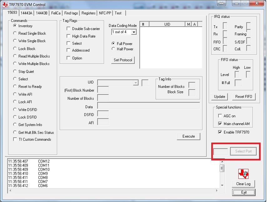
    I have already downloaded program TRF7970A_EVM_GUI.exe (2781184 bytes lenght) and RFIDread Win 7.exe (7887360 bytes), but I have issues with running them on Win 7. In case I connect TR7970A EVM board into USB and COM port e.g. 11 or 35 is assigned, after pressing "Set Protocol" button is program frozen. I tried 32 and 64 bit windows 7 - the same behaviour.

    Output from log file, the EVM board used COM11, after crashing I remapped the com port to COM2 - no success. I don't understand, why Select port button is not working...

    11:10:47.255    COM12
    11:10:47.257    COM11
    11:10:47.258    COM10
    11:10:47.259    COM9
    11:10:47.259    COM8
    11:10:47.260    COM7
    11:10:47.261    COM6
    11:10:47.261    COM5
    11:10:47.262    COM4
    11:10:47.263    COM3
    11:10:47.264    COM2
    11:10:47.265    COM1
    11:10:47.279    --> 0108000304FF0000
    11:10:49.387    *** Read TIMEOUT ***
    11:10:49.407    COM0
    11:10:53.349    --> 010A0003041001210000
    11:10:53.363    COM1
    11:11:35.890    *** Read TIMEOUT ***
    11:11:35.902    --> 010C00030410002101000000
    11:12:18.416    *** Read TIMEOUT ***
    11:12:18.429    --> 0109000304F0000000
    11:13:00.944    *** Read TIMEOUT ***
    11:13:00.948    --> 0109000304F1FF0000
    11:13:43.454    *** Read TIMEOUT ***
    11:13:43.477    --> 010B000304140401000000
    11:14:25.992    *** Read TIMEOUT ***

  • Hello Ondrej,

    Okay two separate points here from my point of view.


    1. How to configure the TRF7970A for reading ISO15693 tags

    The best way to handle this would be to reference our latest example firmware for reading RFID tags: http://www.ti.com/lit/zip/sloc297

    That firmware is designed to show the entirety of the process for activating and reading data for each tag type supported including ISO15693.

    Do NOT use the TRF7970AEVM firmware as a basis for your firmware design!!! It is old, outdated, and the EVM has been obsoleted. The firmware has multiple bugs. The only reason it even lasted as long as it did is because it was used to support another NFC device...

    Please, use SLOC297, and go through the iso15693.c for details on commands to send out. That will give you everything you need.

    I'll note you may want to skip over anticollision initially, while learning, as the function includes an optimized algorithm and is more daunting to understand. You won't need anticollision to start with as long as you only use one tag at a time.


    2. How to use the TRF7970AEVM GUI

    While I don't recommend you using the EVM for your firmware development, I'll still address your question regarding it's operation. Moving the EVM to COM2 is a good step, but I think you need to install the SiLabs driver for the FTDI chip on the EVM to get it working: https://www.silabs.com/products/mcu/pages/USBtoUARTbridgeVCPdrivers.aspx

    You also need to be sure that the default firmware is still loaded into the EVM, anything other than the default firmware may result in the EVM not connecting to the GUI.

  • Hello Ralph,
    I thank you for your help. I appreciate it. I looked into iso15693.c - there is function "uint8_t ISO15693_sendSingleSlotInventory(void)", so it will help me.

    Regarding item 2 - driver for USB/UART is already installed, I see it in the Device Manager, that removing and pluging the TRF7970A EVM board to USB terminal shows adding and removing COM port with certain number. Original vas 11, then I changed it to 2. There is probably issue in the EXE file. I see, it tries COM0 and COM1, not more. When I use just EVM board with COM11, the program reports Missing COM port. If I insert my laptop into docking station and COM1 is added (due to fixed hardware), EVM software is trying to search for enswer from EVM board, but in this phase is program frozen. I don't see available option on the right side of the program for selecting correct COM port.

    My intention with EVM was to connect my scope to SPI bus and record all traffic to see, what numbers are send and received to understand TRF7970A setting procedure and sequence. I tried to recompile source code for EVM GUI software, but I have just Express edition of Microsoft VC++ and some files are missing.

    Thanks,
    Ondrej
  • Hello Ondrej,

    That's an odd situation with the EVM. I can say that COM11 rarely has worked even though the GUI says it tries for that so you'll want to avoid that one - that is why the program reports the Missing COM port. You could also try other ports like COM3 or COM4 in case something weird got hosed up with COM2. When doing so, make sure the GUI is closed. Another option would be to restart your PC to free up the list of COM ports, and then re-plug the EVM in, make sure it enumerates to a low power (COM2-5 range) and then try the GUI again.

    I'm not sure when the last time I tried to build the GUI was, again at this point we consider it an obsolete EVM so while I can offer advice on how to try and make it operate, we aren't investing any time in looking into any bugs.

    As far as scoping the SPI bus, again since that software is not the latest and has bugs, I wouldn't recommend relying on it to do that. This hardware package will work with SLOC297 firmware, that'd be better to use for SPI bus scoping:

  • Hello Ralph,

    thanks again for your support. I'm trying to undertstand source code in SLOC297 bundle, because I'm porting it to ESP32 platform. That means, I have to study, how it works - part for ISO15693. One part of code I don't understand - I know, that TRF7970A generates IRQ signal after receiving command for Inventory and it generates IRQ when data are ready in FIFO buffer. But, looking into "trf79xxa.c" and "iso15693.c" file, I see calling functions waiting for IRQ inside function "TRF7970A_waitRxData"

       case TX_WAIT:
          TRF7970A_waitTxIRQ(ui8TxTimeout);      // TX timeout
          TRF7970A_waitRxIRQ(ui8RxTimeout);      // RX timeout
          break;

    With following parameters in "ISO15693_sendSingleSlotInventory" -

    g_sTrfStatus = TRF7970A_waitRxData(5,15);

    But, looking into SPI bus sniffed by scope - IRQ signal after sending Inventory command (TX) is active approx. after 4.5ms, OK, but IRQ confirming RX is after 50ms after TX IRQ. When both functions for IRQ signal follows in order, there MUST BE timenout generated - RX timeout is set just for 15ms in SLOC297 example. I dont have the TRF7970A BNDL, could somebody verify functionlality of your demo code for TI RFID tag ISO15693 with Inventory command ? - especially IRQ timing ?

    Thanks,

    Ondrej

    43.98ms Serial1 8F 91 3D 00 30 26 01 00 00 00 00 00 00 00 00 00 0
    49.44ms Serial1 4C 00 00 00 80 00 1
    50.87ms Serial1 8F 0 0
    78.94ms Serial1 4C 00 00 00 00 00
    92.34ms Serial1 4D 00 00 0D 3F 6C 00 00 00 3E 3E 00 00 00 00 3E
    93.78ms Serial1 8F 91 3D 00 30 06 01 00 00 00 00 00 00 00 00 00 0
    99.46ms Serial1 4C 00 00 8F 00 80 00 00 1
    118.2ms Serial1 4C 00 00 00 00 00 0
  • Hello Ondrej,

    That timing tells me that the IRQ interrupt is not serviced quickly, which can be a big problem. Even the TX Complete interrupt takes a long time to service.

    For a normal system running SPI at 2MHz, it should take approximately 1.6ms to get a TX complete interrupt, and then only 4-4.5ms more to get an RX complete from receiving the Inventory response.

    I am attaching a capture illustrating the ISO15693 timings for Inventory, Get System Info, and Read Single Block using a TI Tag-It HF-H Pro transponder as the target.

    You can view the capture with the latest Saleae Logic software from: https://www.saleae.com/downloads

    ISO15693_Inventory_Read_Data.logicdata

  • Hello Ralph,
    I'm little bit further now :)
    I have ordered original DLP-7970ABP module and I'm adapting SLOC297 firmware to Arduino.
    Reading is working very well. But writing...

    I'm using funtion uint8_t ISO15693_sendWriteSingleBlock(uint8_t ui8ReqFlag, uint8_t ui8BlockNumber, uint8_t ui8BlockSize, uint8_t * pui8BlockData)

    What is not clear for me is ui8ReqFlag. There is not too much explanation, what is structure of this variable/tag. Could you be more specific ?
    When I try to write to my tag, flag is defined. 0x40 must be set - looking into source code - it announces writing operation
    uint8_t ui8AddressedFlag = B01100010;
    but after writing the first sequence, the data are in the tag - verified by reading - but I receive [01 13] response, what is probably "Programming was unsuccessful" - TRF 7960 Evaluation module (ISO 15693 Host commands) PDF file - page 23.

    Could you explain me, what is the reason of this answer or explain me detailed structure of TRF7970A buffer for writing single address ?

    Thanks,
    Ondrej

  • Hello Ondrej,

    That is the variable for the ISO15693 Request Flags. The required flags for writing can vary from tag to tag. With the flags set to 0x62, that means bit 6 is set to 1 which indicates to the firmware that the Option flag is used for write operation and affects how the command is issued, however that is needed for TI Tag-It HF-I transponder but not many others. You may just want to use 0x22 for writing which is Addressed Mode+High Data Rate.

    The whole range of Request Flags are covered within the ISO15693-3 specifications, which is why we don't have further documentation on that as it is expected that the official ISO standards are referenced for such information along with the tag data sheet to understand the requirements for writing to it.
  • Hi Ralph,

    thanks for explanation. But, still don't know, why my write command is not successful.

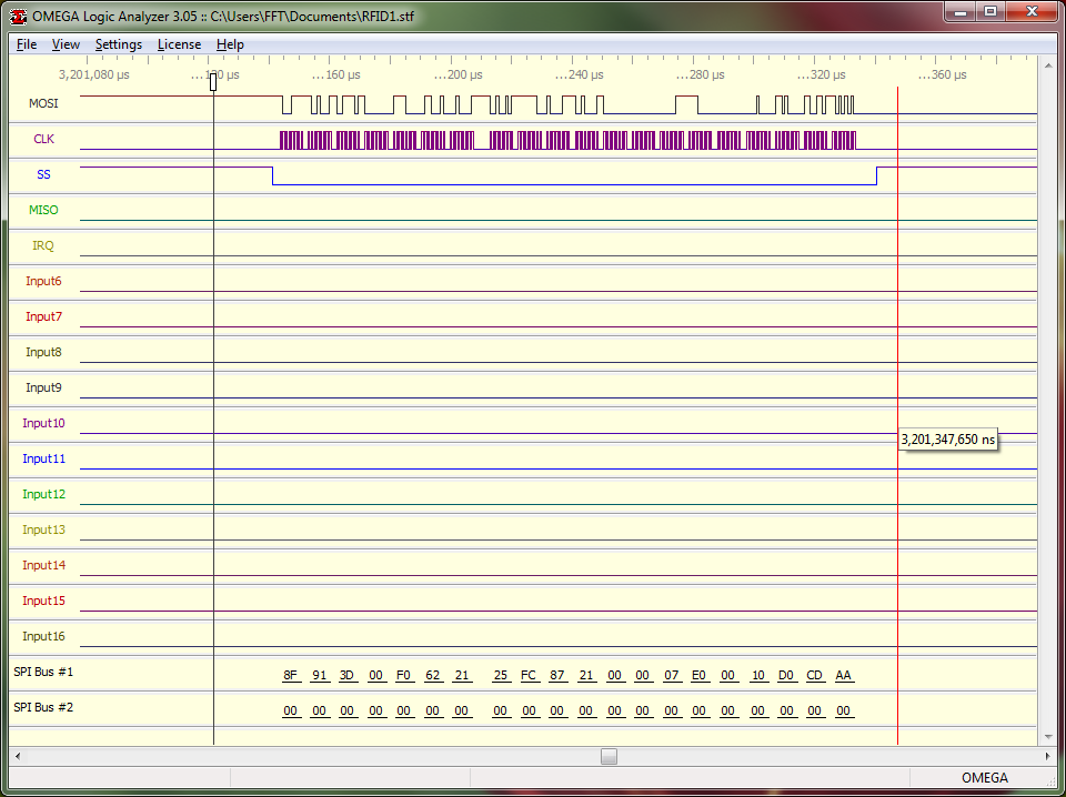
    I'm sending to TRF7970A with UID "E00700002187FC25" following sequence (verified on logic analyzer )

    MISO: 8F 91 3D 00 F0 62 21 25 FC 87 21 00 00 07 E0 00 10 D0 CD AA - is should be request for writing 10 D0 CD AA to block 00

    answer is

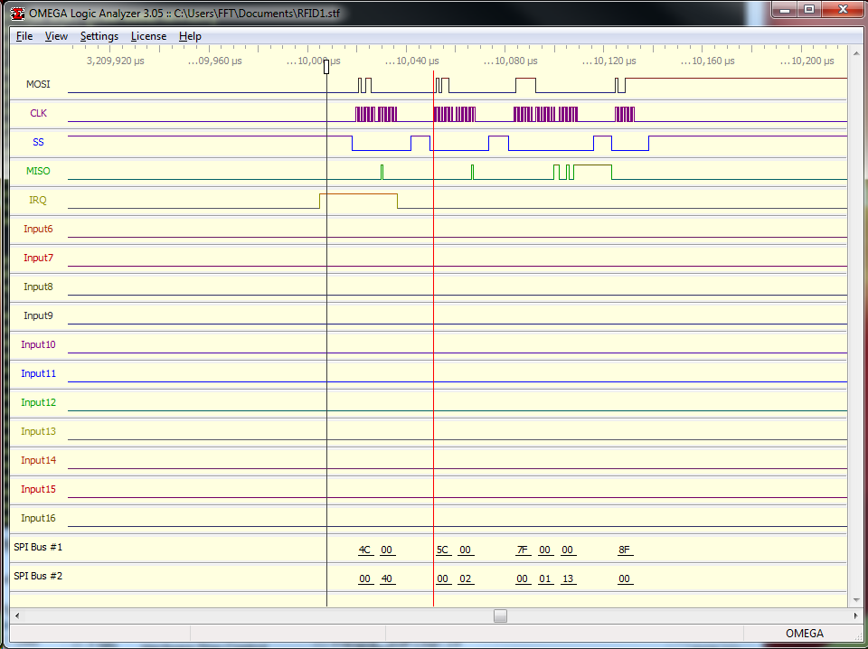
    IRQ -> confirming TX

    MISO 4C 00 5C 00 7F 00 00 8F

    MOSI 00 40 00 02 00 01 13 00

    IRQ -> confirming RX

    MISO 4C 00 5C 00 7F 00 00 8F

    MOSI 00 40 00 02 00 01 13 00

    I tried flag byte 0x22 instead of 0x62, also 0x20 for lower speed - no success.

    Why the answer is not 00 -> OK, but 01 13 - Programming was unssuccesful. What can be wrong ?

    Thanks,

    Ondrej

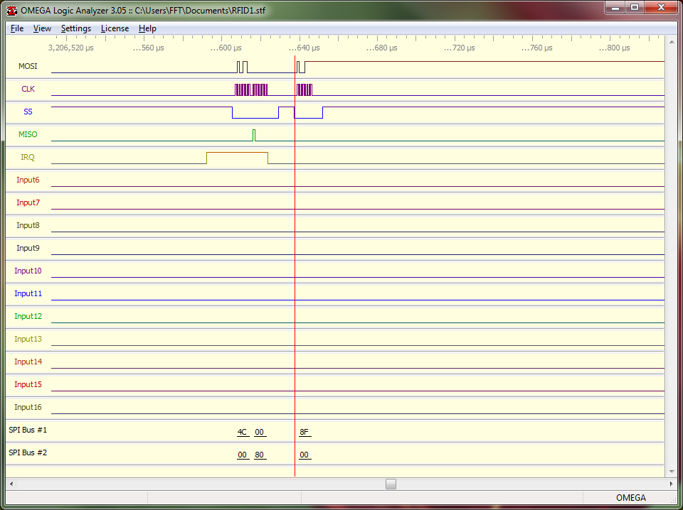
    after the first IRQ

    after the second IRQ

  • Hello Ondrej,

    The flags for 0x62 should result in an EOF command being issued between TX Complete and RX Complete. Does the scope captures look the same when using 0x22 for the flags?
  • Ralph,

    just for my info - how to lock and unlock some block in RF-TAG ? Maybe, I have locked the RFID tag and it is the reason, why I can't write to the memory block. But I don't know how to obtain info, if some block is locked or not. What is the commend or method to unlock it ?

    SPI bus screenshot for flag 0x22 I will send tomorrow, but I expect the same behavior. System reports Status = 0x09, what means  NO_RESPONSE_RECEIVED_15693

    I will investigate it tomorrow. Just I would like to be sure to eliminate situation with locked RFID tag memory.

    typedef enum
    {
        TRF_IDLE,                    // New
        TX_COMPLETE,                // Formally 0x00
        RX_COMPLETE,                // Formally 0xFF
        TX_ERROR,                    // New
        RX_WAIT,                    // Formally 0x01
        RX_WAIT_EXTENSION,            // New
        TX_WAIT,                    // New
        PROTOCOL_ERROR,                // Formally 0x02
        NO_RESPONSE_RECEIVED,        // Formally 0x00
        NO_RESPONSE_RECEIVED_15693     // Added for 15693 cases.
    }tTRF797x_Status;

    Thanks,

    Ondrej

  • Hello Ondrej,

    Few points on that topic:

    1. Lock block cannot be undone, it is permanent.
    2. A tag with a locked block will reply with an error code indicating the block is locked, that is defined by ISO15693 as error code 0x12.
    3. Lock block command is not something I included in the RFID reader code because of how powerful and irreversible it is, so if the tag got locked, it was from some other RFID reader.

    By the way, getting NO_RESPONSE_RECEIVED_15693 should only occur during Anticollision based on how the firmware is structured as it is only used for the No Response Interrupt from IRQ that is disabled by default and only used for the ISO15693 anticollision algorithm.

  • Hello Ralph,

    I did measurement again today. The reality is, although there is error code after operation, the requested value is recorded in the tag. But, I'm still worried about the error code after writing operation.

    The first picture - request to writing to segment 0x00 with flag 0x22

    the first response is IRQ confirming TX + clear FIFO request

    Now, what is not visible, is send 0x94, actually command 0x14 and the second IRQ - RX - is received following error code 0103

    The second try is with flag 0x62 - there is also error reported at the end, but it is different error. See the request, if it is correct.

    confirming TX operation by IRQ, following with clear FIFO request

    and last IRQ confirming RX, see different reported error code. There is also sent 0x94 after TX IRQ (not visible on the picture)

    See different error code. For 0x22 flag it was 0103, for 0x62 flag it is 0113

    Las picture shows whole sequence with timing - sending 0x94 code between TX and RX IRQ - approx. 497.1ms

    The question is, what I'm doing wrong, that after Single write (0x21 command) sequence I receive mentioned errors ? The time delay difference between 0x22 and 0x62 flag option is caused by program structure - fixed value 0x22 and variable with 0x62.

    I tried to find some more info about ISO15693 regarding communication between chip and tag, I'm getting info from SLO141, but is related to host command (software in MSP micro), not direct communication with TRF7970A.

    Thanks,

    Ondrej

  • Hello Ondrej,

    Okay now it becomes crystal clear to me.

    When using flags 0x22 that means Option bit is NOT set and therefore you should NOT issue the 0x14 Direct Command.

    Only when the Option bit is set (Bit 7 in the flags, so 0100 0000) which is done when issuing with 0x62 should the 0x14 Direct Command be issued.

    This is covered accurately in our example code:

    	else if (g_sTrfStatus == TX_COMPLETE)
    	{
    		// Check if the option flag is set
    		if (ui8ReqFlag & 0x40)
    		{
    			MCU_delayMillisecond(10);
    			TRF79xxA_sendDirectCommand(TRF79XXA_TRANSMIT_NEXT_SLOT_CMD);		// Send out End of Frame marker
    		}
    
    		TRF79xxA_waitRxIRQ(30);				// 30 millisecond RX timeout
    	}
  • Hello Ralph,
    any idea, why 0x01 0x13 error code is reported ? (looking to pictures from SPI sniffer)

    O.
  • Hello Ondrej,

    Because of the reason I outlined above - the End of Frame for the Option flag is issued erroneously when the flags are 0x22.
  • Ralph,
    I'm not sure, but you probably looked into bad pictures - there are 7 pictures in my last contribution. The first three pictures are with flag 0x22 - response is 01 03, next 3 pictures are with flag 0x62, the response is 01 13 and the last picture is overall picture with whole sequence to verify timing. In picture 4 you can see flag 0x62 - located on the red line, picture 6 shows FIFO response 00 01 13

    Ondrej

  • Hello Ondrej,

    What ISO15693 tag are you using?
  • Texas Instrument
    RI-IO3-112A-03 (Tag-it HF-I Plus ???)

    Ondrej
  • Hello Ondrej,

    I see, our tags do need the Option Flag feature so the 0x62 w/ EOF sent via 0x94 Command is the correct process for writing them. 0x13 Error indicates the tag was not correctly programmed. Not sure why that is occurring, could be timing related. What is the delay before sending the EOF frame with 0x94 after receiving TX Complete 0x80?
  • Ralph,

    looking to picture 7 of my post with SPI screenshots, the TX IRQ signal is received at 492ms, 0x94 is send at 497.2ms - it means approx. 5ms.

    Ondrej

  • Hello Ondrej,

    Please try to extend the delay between TX Complete and sending the 0x94 to 10ms as done in our example code and see if that fixes the issue.
  • Hello Ralph,

    don't know why, but I used different waiting method in Arduino code than expected "delay(10)" comparing TRF7970A original source code for MSP.

    After replacing original waiting command with delay(10) command it works perfectly now. So the issue was with short time.

    Thanks for your help.

    Ondrej