This thread has been locked.

If you have a related question, please click the "Ask a related question" button in the top right corner. The newly created question will be automatically linked to this question.

LAUNCHXL-CC2650: A problem with baremetal SPI driver

Part Number: LAUNCHXL-CC2650
Other Parts Discussed in Thread: CC2650

Hello,

I have written a small bare-metal application for CC2650 (without RTOS) it works so far, but it has following issues:

After flashing and debugging starts the code shall be reset in another case the DMA do not starts.

If I'm trying to receive something with SPI all of the bytes are shifted ones to the right with padding "0" for first received byte. (e.g. the first value = 0xE1,  SPI  receives 0x70 == 1110 0001 -> 0111 0000) the bit shifted away is present in the next byte.This issue is not dependent on usage of DMA.

An example from RTOS do not have this problems...

Could someone point me on what i have forgot during initialization?

Thanks in Advance.

In following is the code for initialization of components and operation:

/*Initialisation code*/
void init_platform(uint32_t ui32SysClockSpeed) {
  IntMasterDisable();
  SetupTrimDevice();

  appDcdcOn(true);
    // Set Clock frequeuncy
  if(OSCClockSourceGet(OSC_SRC_CLK_HF) != OSC_XOSC_HF) {
    /* Request to switch to the crystal to enable radio operation. */
    OSCClockSourceSet(OSC_SRC_CLK_LF | OSC_SRC_CLK_MF | OSC_SRC_CLK_HF, OSC_XOSC_HF);
    /* Switch the HF source to XTAL - Done via ROM API*/
    OSCHfSourceSwitch();
  }
  
  PRCMInfClockConfigureSet(PRCM_CLOCK_DIV_1, PRCM_RUN_MODE);
  PRCMInfClockConfigureSet(PRCM_CLOCK_DIV_8, PRCM_SLEEP_MODE);
  PRCMInfClockConfigureSet(PRCM_CLOCK_DIV_32, PRCM_DEEP_SLEEP_MODE);
  // set Power for serial CPU
  PRCMPowerDomainOn(PRCM_DOMAIN_CPU);                                           // Activate CPU Domain
  PRCMLoadSet();                                                                // wait on complete
  while(!PRCMLoadGet()); 
  // set Power for serial SYSBUS
  PRCMPowerDomainOn(PRCM_DOMAIN_SYSBUS);                                        // Activate System bus Domain
  PRCMLoadSet();                                                                // wait on complete
  while(!PRCMLoadGet()); 
  // set Power for serial VIMS
  PRCMPowerDomainOn(PRCM_DOMAIN_VIMS);                                          // Activate VIMS Domain
  PRCMLoadSet();                                                                // wait on complete
  while(!PRCMLoadGet());   
  // set Power for serial interfaces
  PRCMPowerDomainOn(PRCM_DOMAIN_SERIAL);                                        // Activate perfirial Domain
  PRCMLoadSet();                                                                // wait on complete
  while(!PRCMLoadGet());
  // set Power MCU domain
  PRCMPowerDomainOn(PRCM_DOMAIN_MCU);                                        // Activate perfirial Domain
  PRCMLoadSet();                                                                // wait on complete
  while(!PRCMLoadGet());
  

// set Power for peripherie
  PRCMPowerDomainOn(PRCM_DOMAIN_PERIPH);                                        // Activate perfirial Domain
  PRCMLoadSet();                                                                // wait on complete
  while(!PRCMLoadGet());
  

  // set Power for timer
  PRCMPeripheralRunEnable(PRCM_PERIPH_TIMER0);                                  // enable clock and all resisters of timer 0  
  PRCMLoadSet();                                                                // wait on complete
  while(!PRCMLoadGet());

  // set Power for GPIO
  PRCMPeripheralRunEnable(PRCM_PERIPH_GPIO);
  PRCMLoadSet();                                                              // Start Clocking
  while(!PRCMLoadGet());                                                      // Check OK
  // set Power for DMA
  PRCMPeripheralRunEnable(PRCM_PERIPH_UDMA);                                  // Enable DMA Pereferie
  PRCMLoadSet();                                                              // Start Clocking
  while(!PRCMLoadGet());                                                      // Check OK

  // set Power for UART
  PRCMPeripheralRunEnable(PRCM_PERIPH_UART0);                                 // Activate UART Power domain
  PRCMLoadSet();                                                              // check..
  while(!PRCMLoadGet());                                                      // wait on check completed
  // set Power for SPI
  PRCMPeripheralRunEnable(PRCM_PERIPH_SSI0);                                  // Activate SPI/SSI Power domain
  PRCMLoadSet();                                                              // check
  while(!PRCMLoadGet());                                                      // wait on check completed
  AONBatMonEnable();
IntMasterEnable();
}

void initUDMA(){

    /* Disable all channels */
    
    bspUDMAChannelDisable(0xFFFFFFFF);

    /* Set the base for the channel control table. */
    uDMAControlBaseSet(BSP_DMA_BASE, (void *) UDMA_CONFIG_BASE);                // Set the Base Address of the DMA Table
    /* Clear UDMA error status and all interrupts*/

    /* Enable uDMA. */    
    uDMAEnable(BSP_DMA_BASE);
}

void bspUDMAConfig(uint8_t *SourceAddress, uint8_t *DistanationAdress, uint8_t NumberOfBytes){
  volatile tDMAControlTable       *dmaControlTableEntry;
 /*Setup receiver Side of the DMA controller */
  dmaControlTableEntry = &dmaSpi0RxControlTableEntry;
  dmaControlTableEntry->ui32Control  = dmaRxConfig[0];
  dmaControlTableEntry->pvDstEndAddr = (void *)((uint32_t)(DistanationAdress) + NumberOfBytes - 1);
  dmaControlTableEntry->pvSrcEndAddr = (void *)(BSP_SPI_BASE + SSI_O_DR);
  dmaControlTableEntry->ui32Control  |= UDMA_SET_TRANSFER_SIZE(NumberOfBytes);
 
  /*Setup transmitter Side of the DMA controller */
  dmaControlTableEntry = &dmaSpi0TxControlTableEntry;
  dmaControlTableEntry->ui32Control  = dmaTxConfig[0];
  dmaControlTableEntry->pvSrcEndAddr = (void *)((uint32_t)(SourceAddress) + NumberOfBytes - 1);
  dmaControlTableEntry->pvDstEndAddr = (void *)(BSP_SPI_BASE + SSI_O_DR);
  dmaControlTableEntry->ui32Control  |= UDMA_SET_TRANSFER_SIZE(NumberOfBytes);
 
   /* Enable DMA channel (quick) */
  HWREG(BSP_DMA_BASE + UDMA_O_SETCHANNELEN) = ((UDMA_CHAN_SSI0_RX_MASK) | (UDMA_CHAN_SSI0_TX_MASK));
  
}

void initSPI(uint32_t ui32SpiClockSpeed, void (*CallBack)(void)) {
  /* Register callback, if present */
  if(CallBack)
    SPICallBack = CallBack;


  /* Set SPI mode and speed */


  /* Disable SSI function before configuring module*/

  SSIDisable(BSP_SPI_BASE);

  /* Disable SPI module interrupts */

  SSIIntDisable(BSP_SPI_BASE, SSI_RXOR | SSI_RXFF | SSI_RXTO | SSI_TXFF);
  SSIIntClear(BSP_SPI_BASE, SSI_RXOR | SSI_RXTO);
    //
    //
    // Configure SSI module to Motorola/Freescale SPI mode 3:
    // Polarity  = 1, SCK steady state is high
    // Phase     = 1, Data changed on first and captured on second clock edge
    // Word size = 8 bits
    //
  SSIConfigSetExpClk(BSP_SPI_BASE, BSP_CLK_SPD_48MHZ, SSI_FRF_MOTO_MODE_3, SSI_MODE_MASTER, ui32SpiClockSpeed, 8);
  IOCPinTypeSsiMaster(BSP_SPI_BASE, BSP_IOID_SPI_MISO, BSP_IOID_SPI_MOSI, BSP_IOID_SPI_CS, BSP_IOID_SPI_SCK);

  
  SPIFlushFifos();
  IntPendClear(INT_SSI0_COMB); 
  IntRegister(INT_SSI0_COMB, bspSpiInterruptHandler);
  IntEnable(INT_SSI0_COMB);
  SSIEnable(BSP_SPI_BASE);

}

void SPI_SendOverDMA(uint8_t *SourceAddress, uint8_t *DistanationAdress, uint8_t NumberOfBytes){
  SSIEnable(BSP_SPI_BASE);
  bspUDMAConfig(SourceAddress, DistanationAdress, NumberOfBytes);
  /* Start transaction due to enabling of the SPI DMA channels*/
  SSIDMAEnable(BSP_SPI_BASE, SSI_DMA_TX | SSI_DMA_RX );
  /* Enable the RX overrun interrupt in the SSI module */
  SSIIntEnable(BSP_SPI_BASE, SSI_RXOR);  //SSI_TXFF | SSI_RXFF |

}

/*Application */
int main()
{
 // Power_init();
  init_platform(BSP_CLK_SPD_48MHZ);

 
  initUDMA();
  initSPI(12000000, 0);
    
  SPI_SendOverDMA(SendArray,ReceiveArray,20);
  while(1) {
    delay--;
    if(!delay) {
       delay = 48000000;
       SPI_SendOverDMA(SendArray,ReceiveArray,20);
       
    }
  }
  return 0;
}


  • Hi,

    Regarding the bit shifting when you try to receive data, can you verify which SSI mode the slave is operating in? It may be different than SSI_FRF_MOTO_MODE_3.

    Regards,

    Toby

  • Hi Toby,

    Yes I have checked this already. I have tryied my driver and oridinal one from RTOS with the same Slave.

    Both of the Masters uses the same mode SSI_FRF_MOTO_MODE_3 (My code) and SPI_POL1_PHA1 (Ti Rtos) and Ti-Rtos driver works.

    Changing of the mode causes much more "errors"

    Best regards

    D.Krush

  • I couldn't find anything missing from your code.

    What SPI clock speed does the example initialize with?

    According to this post:

    e2e.ti.com/.../2152525

    since you are operating in Normal Duplex mode, I would suggest a lower clock speed.

    According to the datasheet (section 6.10):

    http://www.ti.com/lit/ds/symlink/cc2650.pdf

    SSI supports master and slave up to 4 MHz. Try using this value for your SPI clock speed.


    Regards,
    Toby

  • Hi Toby,

    The SPI Clock was initialized to 12 MHz. You mean, 12MBit works only in RX or TX but not in case of Duplex operation?

    I'll check the settings in RTOS project, probably the settings were set to not duplex operation.

    Thank You for reply!

  • Hi Toby
    I have checked the settings. The Project which uses RTOS is able to use the SPI in full duplex mode with 12 MBit. It sends and receives 20 bytes of data as one transaction. All of the bytes are received by SPI-Master and SPI-Slave correctly.
    I think there is some register setting programmed during the BIOS initialization, which I do not know...
    Best Regards
    D.Krush
  • Hi D.Krush,

    Does your baremetal SPI driver work when you lower the SSI clock (eg, to 4 MHz or less)?

    Can you provide me the example code you mention?

    Regards,

    Toby

  • Hi Toby,

    I have made some measurements => the BareMetal code, I'm using, is able to work with up to 8 MBit, but not with 12 MBit I prefer.

    The example code form RTOS is taken from the standard SPI example (for LCD display) I'll provide the functions were relevant for initialization and data exchange.  

    (The example code will be as a text document, the "insert code" functionality was not working for me...

    Code.txt
     
    #include <ti/drivers/power/PowerCC26XX.h>
    /*
     *  ============================= UDMA begin ===================================
     */
    /* Place into subsections to allow the TI linker to remove items properly */
    #if defined(__TI_COMPILER_VERSION__)
    #pragma DATA_SECTION(UDMACC26XX_config, ".const:UDMACC26XX_config")
    #pragma DATA_SECTION(udmaHWAttrs, ".const:udmaHWAttrs")
    #endif
    
    /* Include drivers */
    #include <ti/drivers/dma/UDMACC26XX.h>
    
    /* UDMA objects */
    UDMACC26XX_Object udmaObjects[CC2650_LAUNCHXL_UDMACOUNT];
    
    /* UDMA configuration structure */
    const UDMACC26XX_HWAttrs udmaHWAttrs[CC2650_LAUNCHXL_UDMACOUNT] = {
        {
            .baseAddr    = UDMA0_BASE,
            .powerMngrId = PowerCC26XX_PERIPH_UDMA,
            .intNum      = INT_DMA_ERR,
            .intPriority = ~0
        }
    };
    
    /* UDMA configuration structure */
    const UDMACC26XX_Config UDMACC26XX_config[] = {
        {
             .object  = &udmaObjects[0],
             .hwAttrs = &udmaHWAttrs[0]
        },
        {NULL, NULL}
    };
    /*
     *  ============================= UDMA end =====================================
     */
    
    /*
     *  ========================== SPI DMA begin ===================================
     */
    /* Place into subsections to allow the TI linker to remove items properly */
    #if defined(__TI_COMPILER_VERSION__)
    #pragma DATA_SECTION(SPI_config, ".const:SPI_config")
    #pragma DATA_SECTION(spiCC26XXDMAHWAttrs, ".const:spiCC26XXDMAHWAttrs")
    #endif
    
    /* Include drivers */
    //#include <ti/drivers/spi/SPICC26XXDMA.h>
    #include "spi/SPICC26XXDMA.h"
    
    /* SPI objects */
    SPICC26XX_Object spiCC26XXDMAObjects[CC2650_LAUNCHXL_SPICOUNT];
    
    /* SPI configuration structure, describing which pins are to be used */
    const SPICC26XX_HWAttrs spiCC26XXDMAHWAttrs[CC2650_LAUNCHXL_SPICOUNT] = {
        {
            .baseAddr           = SSI0_BASE,
            .intNum             = INT_SSI0_COMB,
            .intPriority        = ~0,
     //       .swiPriority        = 0,
            .powerMngrId        = PowerCC26XX_PERIPH_SSI0,
            .defaultTxBufValue  = 0,
            .rxChannelBitMask   = 1<<UDMA_CHAN_SSI0_RX,
            .txChannelBitMask   = 1<<UDMA_CHAN_SSI0_TX,
            .mosiPin            = Board_SPI0_MOSI,
            .misoPin            = Board_SPI0_MISO,
            .clkPin             = Board_SPI0_CLK,
            .csnPin             = Board_SPI0_CSN,
        },
        {
            .baseAddr           = SSI1_BASE,
            .intNum             = INT_SSI1_COMB,
            .intPriority        = ~0,
        //    .swiPriority        = 0,
            .powerMngrId        = PowerCC26XX_PERIPH_SSI1,
            .defaultTxBufValue  = 0,
            .rxChannelBitMask   = 1<<UDMA_CHAN_SSI1_RX,
            .txChannelBitMask   = 1<<UDMA_CHAN_SSI1_TX,
            .mosiPin            = Board_SPI1_MOSI,
            .misoPin            = Board_SPI1_MISO,
            .clkPin             = Board_SPI1_CLK,
            .csnPin             = IOID_UNUSED,//Board_SPI1_CSN
        }
    };
    
    /* SPI configuration structure */
    const SPI_Config SPI_config[] = {
        {
             .fxnTablePtr = &SPICC26XXDMA_fxnTable,
             .object      = &spiCC26XXDMAObjects[0],
             .hwAttrs     = &spiCC26XXDMAHWAttrs[0]
        },
        {
             .fxnTablePtr = &SPICC26XXDMA_fxnTable,
             .object      = &spiCC26XXDMAObjects[1],
             .hwAttrs     = &spiCC26XXDMAHWAttrs[1]
        },
        {NULL, NULL, NULL}
    };
    /*
     *  ========================== SPI DMA end =====================================
    */
    /*
    * ========================== Callback SPI start ================================
    */
    extern uint32_t SPI_START;
    void spiHWI(SPI_Handle handle, SPI_Transaction * transaction) {
    // ToDo Set Flags, Evaluate received data...
    }
    
    /*
    * ========================== Callback SPI end ==================================
    */
    
    
    /*
     *  ======== SPI_Init ========
     *  This function initialize SPI Periphery
     *  SPI Periphery : SSI0_BASE
     *  SPI Speed : SPI_Bit_Rate = 12 000 000 -> 12MBit
     *  SPI Data Size : 8 Bit
     *  SPI Mode : MASTER
     *  SPI Transfer Mode : CALLBACK
     *  SPI Foramet : POLARITY = 1 PHASE = 1
     * 
     */
    bool SPI_Init() {
    
      SPI_init();
      SPI_Params_init(&spiParams);   // set default
      spiParams.bitRate = SPI_Bit_Rate; // 12000000 -- 12 MBit!
      spiParams.dataSize = 8;
      spiParams.frameFormat = SPI_POL1_PHA1;
      spiParams.mode = SPI_MASTER;
      spiParams.transferMode = SPI_MODE_CALLBACK;
      spiParams.transferCallbackFxn = spiHWI;                                         
      spiHandle = SPI_open(SSI0_BASE, &spiParams);
      if (!spiHandle)
      {
          return false;
      }
      return true;
    }


    /*
     *  ======== IOLW_SPI_Receive_Array ========
     *  This function sends @e usLen bytes from @e *Addr and receives @e usLen bytes to
     *  @e pcData over SPI. 
     */
    bool IOLW_SPI_Receive_Addr_Array(const char *Addr, const char *pcData, unsigned short usLen){
          /* Do SPI transfer */
        SPI_Transaction spiTransaction;
        spiTransaction.arg = NULL;
        spiTransaction.count = usLen;
        spiTransaction.txBuf = (Ptr)Addr;
        spiTransaction.rxBuf = (Ptr)pcData;
        bool ret = SPI_transfer(spiHandle, &spiTransaction);
        if(ret == false){
            return false;
        }
    
        return true;
    }
    
    /* ......  ....... */
    
    #define PAYLOAD_LENGTH 20
    Task_Struct Task_t;
    uint8_t TaskEnable_old = FALSE;
    Char myTaskStack[512];
    
    uint8_t txPayload[PAYLOAD_LENGTH];
    uint8_t rxPayload[PAYLOAD_LENGTH] = {0x01,0x02,0x03,0x04,0x05,0x06,0x07,0x08,0x09,0x0A,    
                                         0x0B,0x0C,0x0D,0x0E,0x0F,0x10,0x11,0x12,0x13,0x14};
    
    int main() {
        Task_Params taskParams;
        TaskEnable = TRUE;
        TaskEnable_old = FALSE;
        /* Configure task. */
        Task_Params_init(&taskParams);
        taskParams.stack = myTaskStack;
        taskParams.stackSize = sizeof(myTaskStack);
        taskParams.priority = 3;
        Task_construct(&Task_t, MainTask, &taskParams, NULL);
    
        BIOS_start();
        /* Should never get here, keep compiler happy */
        return SUCCESS;
    }
    
    static void MainTask(UArg a0, UArg a1)
    {
      PRCMPowerDomainOn(PRCM_DOMAIN_SERIAL);
      Power_setConstraint(PowerCC26XX_IDLE_PD_DISALLOW);
      Power_setConstraint(PowerCC26XX_SB_DISALLOW);  
      SPI_Init();
      SPI_Receive_Addr_Array(rxPayload, txPayload, PAYLOAD_LENGTH);
      while(1)
      {
        for(int i = 0; i< 48000000; i++); // wait for a while...
        SPI_Receive_Addr_Array(rxPayload, txPayload, PAYLOAD_LENGTH);
      }
    }
    
    )

  • Hi,

    SPI at 12 Mhz as a master should work. As a slave, no chance, since the SPI module needs to oversample MISO an SCK 4x and the SPI internal clock is 12 MHz.  

    If it works with the TI driver, but not with your own bare-metal implementation, please go through all registers and check if there is any difference just before you start the transfer. You can step-debug through the SPI driver by copying SPICC26XXDMA.c from the SDK into your project and compile it along. Then you should be able to stop the application in SPICC26XXDMA_transfer(). Focus on the SPI peripheral registers. Is the clock polarity and phase really the same?

    Did you also check with a logic analyzer? What is happening on the SPI bus when the transfer starts? Is there something different between the two versions on signal level? Is there any spike, for instance on the SCK line at the start of the transfer, maybe due to IO configuration?

    It think it makes most sence to look at the signals first. The problem as you describe it, that the first transaction fails, sounds like intial IO configuration is the root cause.

  • Hi Richard,

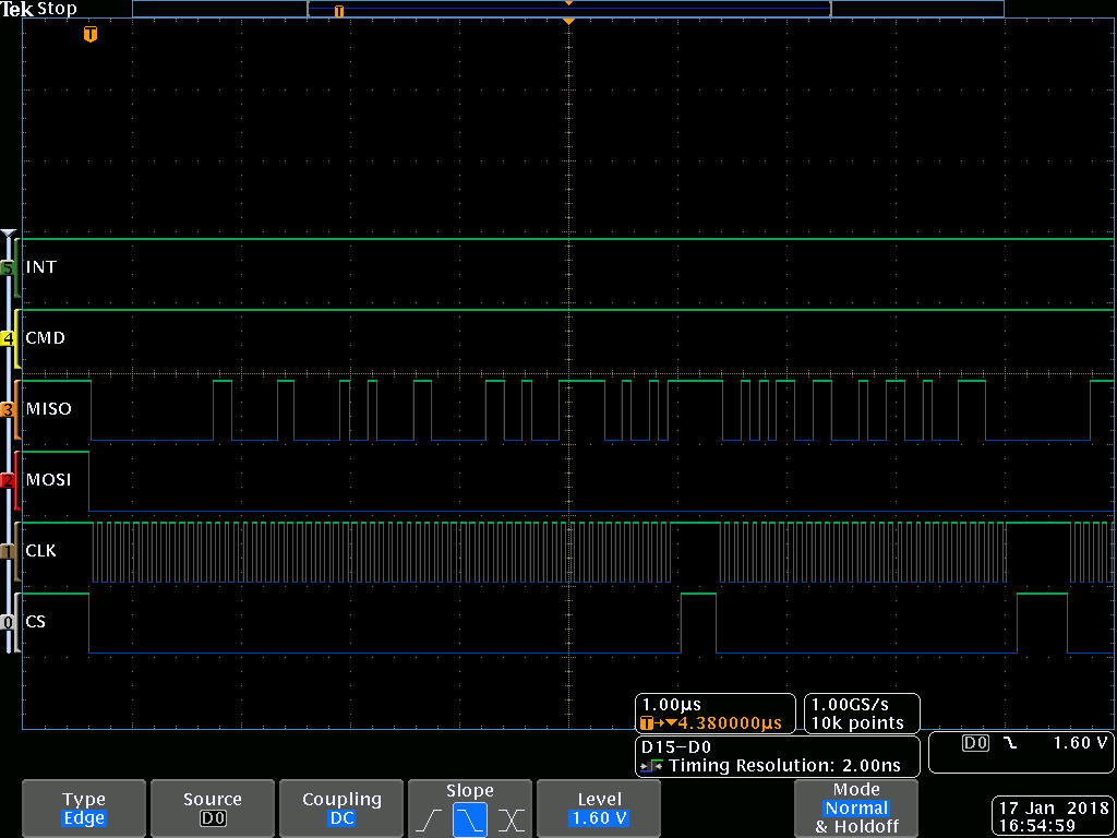
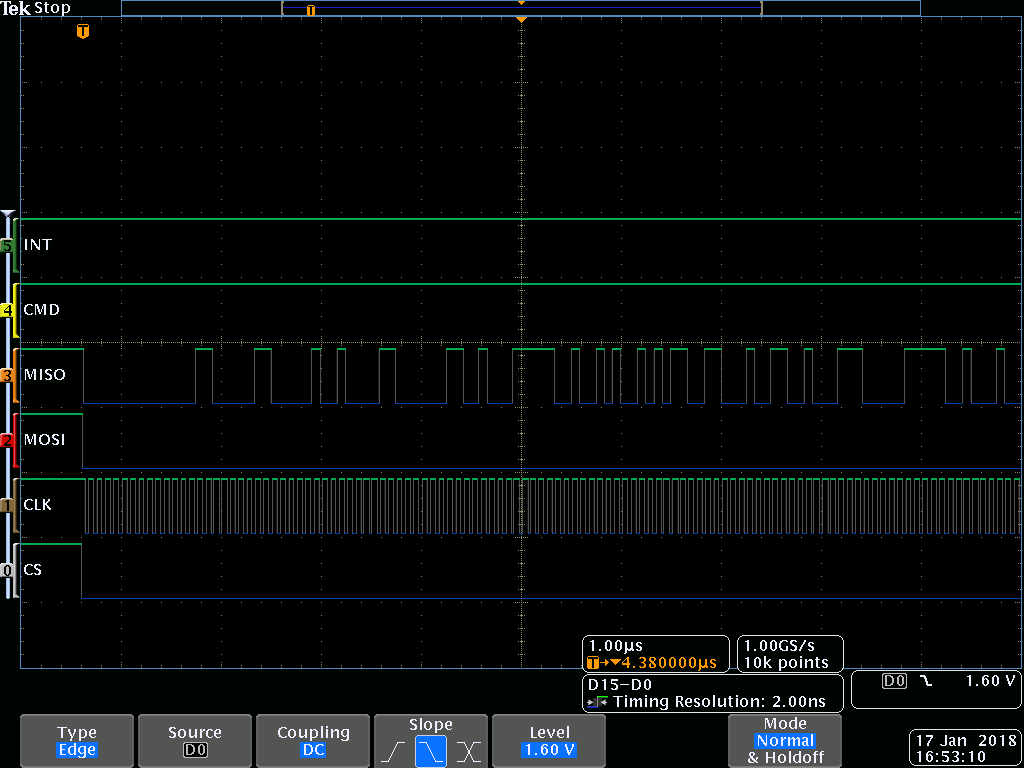
     I have checked the SPI transactions with logic analyzer for both RTOS, and BareMetal solutions. They are absolutely identical:

    SPI by RTOS ->

    SPI BareMetal:

    only difference You can see is the CS line and it's caused by BUS arbitration in RTOS.

    I think I gave not 100% correct description about the first SPI transaction: SPI periphery sends all bytes without any issues, but the DMA does not generate RX-Channel-Done interrupt in the first transaction as if the last byte is not received completely. In the following transactions this interrupt is always generated.


    I'm speculating: the last bit of the byte stays in the shift register of SPI periphery and the periphery does not generate RX done, that means the first RX transaction cannot complete, the next transactions uses this bit as the first bit of it's first byte and so on.


    Another speculation: the fist bit is always not received, after first byte reception only 7 bits are available in the shift register of SPI periphery (byte is not complete) all next byte-receptions shifts bits from periphery register away and on the end it has 7 bits in shift register, that means the first RX transaction cannot complete, the next transactions uses this bits as initial value for the first byte reception and so on.

    I'm not sure that I can check both of the Speculation, but I'll try to do so.

    If it can help, I can send You the whole project as link on Your e-mail.

    Best Regards,

    And grate thanks for reply

    D.Krush

    Update: I have checked the register settings, they are identical. RTOS and BareMetal has right values:

    SSI0_CR0 = 0x01c7 //(0x40000000)

    SSI0_CR1 = 0x0002 //(0x40000004)

    SSI0_SR   = 0x0003 //(0x4000000C)

                        0x0002 //(0x40000010)

    SSI0_IMSC = 0x0008 //(0x40000018)

    Best Regards

  • I think I have found the solution. You were right with the idea to check the IO config.

    The SPI works with 12 Mbit only if the PIN current is >= 4 mA and input pin is set to IOC_PULL_DOWN.

    Normally, if someone uses the provided low level driver, the driver will automatically select 2 mA current and the input pin receives IOC_NO_IOPULL configuration, which cause the problem if the bit rates > 8 Mbit.

    To work with 12 MBit SPI Master in the BareMetal application the following shall be done:
    Create two new defines :

    #define IOC_SPI_INPUT        (IOC_CURRENT_2MA  |  IOC_IOPULL_DOWN |  IOC_INPUT_ENABLE ) // 0x20002000
    
    #define IOC_SPI_OUTPUT       (IOC_NO_IOPULL | IOC_CURRENT_4MA )                         // 0x00006400


    and use them to configure the Pins. For example, if the SPI uses the pins:

    #define MOSI_PIN     9
    #define MISO_PIN     8
    #define CS_PIN       11
    #define CLK_PIN      10


    the configuration is the following (the code is taken from IOCPinTypeSsiMaster( ... ) from file ioc.c )

            if(MISO_PIN!= IOID_UNUSED)
            {
                IOCPortConfigureSet(MISO_PIN, IOC_PORT_MCU_SSI0_RX, IOC_SPI_INPUT);
            }
            if(MOSI_PIN!= IOID_UNUSED)
            {
                IOCPortConfigureSet(MOSI_PIN, IOC_PORT_MCU_SSI0_TX, IOC_SPI_OUTPUT);
            }
            if(CS_PIN!= IOID_UNUSED)
            {
                IOCPortConfigureSet(CS_PIN, IOC_PORT_MCU_SSI0_FSS, IOC_SPI_OUTPUT);
            }
            if(CLK_PIN!= IOID_UNUSED)
            {
                IOCPortConfigureSet(CLK_PIN, IOC_PORT_MCU_SSI0_CLK, IOC_SPI_OUTPUT);
            }

    Best regards D.Krush