This thread has been locked.

If you have a related question, please click the "Ask a related question" button in the top right corner. The newly created question will be automatically linked to this question.

CC3220MODA: - Serial flash: clarification about serial FLASH compatibility ? Uniflash access to Serial Flash?

Part Number: CC3220MODA
Other Parts Discussed in Thread: UNIFLASH, CC3220S

Team,

In case you want to use a different serial Flash device then some information about command that need supported by the flash are provided at:
http://www.ti.com/lit/an/swra515a/swra515a.pdf
at section "1.2 Supported Flash Types".

I assume that the IO voltage, SPI timing compatibility and the support of those commands are the only requirement in term of HW. Correct?
Or are there additional requirements not documented?

In term of TI SW (API that access the serial flash via SPI):
-Are there some additional requirements like for example in the Device ID value returned by the Flash?
-Is the SPI driver source code (used in ROM bootloader, Uniflash API, ..etc) available somewhere to check if there are such requirements?

[edited to add more information]

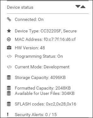
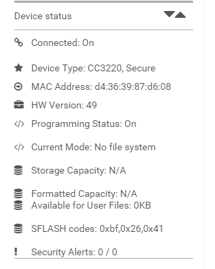
The issue occurs when we use UniFlash and try to connect to the CC3220S. The connection works fine but it shows under device status that it has not found any flash device to load programs/certificates on.
I did some checking on the SPI data, with a logic analyzer, what was sent and I noticed a difference in the data that returned from 0x9F command(JEDEC ID) if I compared the working flash (S25FL116K) and the none working flash (SST26VF016).
The datasheet does not specify anything about the data that is returned from the 0x9F command but it seems that the CC3220/UNIFLASH does require a specific format.
Are there documentation about it?
Is the SPI driver used by uniflash available to check this?

Thanks in advance,

Anthony

  • Hi AnBer,

    Thanks for your question. Please allow us some time to get back to you with a detailed response.
  • AnBer,

    You can find more information about the returned value in the datasheets for the flash parts you are inspecting. Command 0x9F (JEDEC ID) should read manufacturer and device ID, so I would expect these to be different between the two devices.

    Please note, as mentioned in the app note, "serial flash components from some vendors may appear to be equivalent in memory capacity, but after close examination of the serial flash data sheets can reveal significant parametric differences between components in areas such as operating voltage and access times."

    Please take this into consideration as well.
  • Hi Austin,

    Thanks for your reply. I know that there are differences in the JEDEC ID for both chips but the size that is returned is for both the same 3 bytes. The App note states: "Command 0x9F (read the device ID [JEDEC]). Procedure: SEND 0x9F, READ 3 bytes". However I think it is a bit more complex than that. I think that UNIFLASH uses the JEDEC ID to determine the size of the flash because that can be returned in the third byte of the JEDEC ID. 

    S25FL116K JEDEC return format:

    9Fh(3) Manufacturer ID = 01h Device Type = 40h Capacity = 15h(this is excepted by UNIFLASH)

    ISSI IS25LQ016B

    Device ID (ID7-ID0)    Memory Type     Capacity (ID15-ID0)  (this is excepted by UNIFLASH)

    14h                                   40                           15h

    SST26VF016B JEDEC return format:

                    Product Manufacturer ID (Byte 1) Device Type (Byte 2) Device ID (Byte 3) (this is not excepted by UNIFLASH

    SST26VF016         BFH                                      26H                           01H

    As you can see in the examples above it seems like UNIFLASH uses the 3rd byte to determine flash size.

    However I would like to know this for sure and it would be good I thing to inform your users about this because it helps with selecting a correct FLASH chip.

    Kind Regards,

    AG

  • Hi AnBer + Art,

    I hear your concern and want you to know that I'm looking into your question on whether the 3rd byte is used to determine flash size.
  • Hi Art,

    Thanks for confirming that you use both ISSI IS25LQ016B and Microchip SST26VF016 for  the testing.

    Regarding Uniflash:
    Could you please clarify what "size flash" settings do you use for the image creation?
    http://processors.wiki.ti.com/index.php/CC3100_%26_CC3200_UniFlash#Image_Creation_and_Programming
    http://processors.wiki.ti.com/index.php/CC3100_%26_CC3200_UniFlash#Settings

    Thanks,

    A.

  • Hi Art,

    Some more feedback:

    From what I understand, there are three possibilities for obtaining the flash size:

    1. The Uniflash tool uses the device read command to set the flash size.

    2. If there is an issue reading the device information, then the tool will mention this and ask the user to set the storage size manually in the Image Creator tool.

    3. Lastly, if the device read was successful, the user can still manually over write the flash size parameter by choosing the same or less flash storage.  As an example in the below screenshot I was able to manually set the formatted capacity to 2MB, despite having an available capacity of 4MB.

    Based on the SPI captures it seems that you get the correct manufacturer device ID (as from flash datasheet) returned from the JEDED-ID read command (0x9F). This suggests there is a different issue with the flash itself causing the error “has not found any flash device to load programs/certificates on.”


    Can you check with the flash manufacturer if there are difference between the SST26VF016 (NRND) and the SST26VF016B (ACTIVE)?
    Since you test SST26VF016  there might still be difference with SST26VF016B  that you will use in prod.

    A.

  • Hi AnBer,

    After your explanation I soldered and tested one of the SST26VF016B chips. It gave the following results:

    There is no flash detected:

    When I try to program it gives me the following error:

    Any idea what can cause this error ?

    Kind Regards,

    AG

  • I also found that the SST26VF016B  protects all blocks by default at startup.

    quote from datasheet: "the device is write-protected by default after a power-on reset cycle. A Global Block-Protection Unlock command offers a single command cycle that unlocks the entire memory array for faster manufacturing throughput."

    Could that be a problem for the CC3220S/UNIFLASH?

  • Art,

    It seems that from CC3220 uniflash is always unlocking the flash before writing so it should not be an issue.

    -How long does it take to get the error message after you hit the program button?
    -Could you create a new uniflash project and simply connect and program without adding any file to the project. Any error or message?

    Thanks,

    Anthony