This thread has been locked.

If you have a related question, please click the "Ask a related question" button in the top right corner. The newly created question will be automatically linked to this question.

XTR115 followed by a step-down converter

Other Parts Discussed in Thread: XTR115, TPS54062

Hi,

I like to use the XTR115 (or 116/117)  followed by a step-down converter (for example TPS54062) to build a 4-20mA 2-wire HART Transmitter.

The following converter should be used to generate a 3,3V Voltage with current higher than 4 mA.


The step-down converter is connected to the XTR-Pins 7 (7,5 – 36V) and Pin 3(IRet).

The TPS54062 datasheet says, it requires a input decoupling capacitor of at least 1µF.

The XTR115 don’t like larger capacitors between Pins 7  (V+) and Pin 4(IO). The capacitor at the input pins should be 10nF or 1nF with HART.

How do I handle the problem with the input capacitors? Is there an application note available on how to connect the XTR with a step-down converter?

Is there any other XTR that works with a converter and HART?

Thanks

Martin

  • Hello Martin,

    I spent some time looking at the TPS54062 and I'm having some trouble understanding how you intend to use it as a HART Modem.  Would you please sketch out an example of what you're system would look like?

    Thanks,
    Collin Wells

  • Hi Collin,

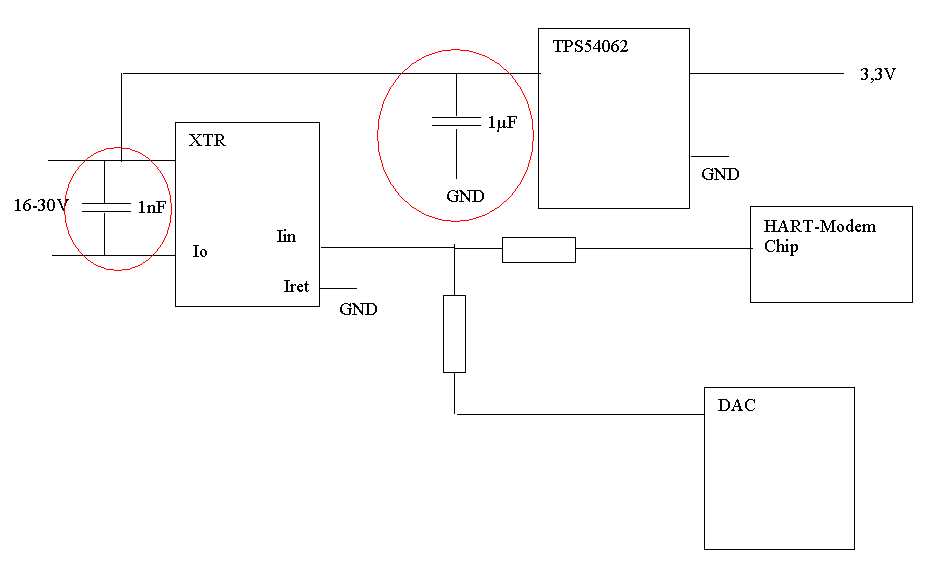
    sorry for the misleading discription. Here is a sketch of the parts that I want to use.

    I just draw it in Office, because I have no access to my original schematic fom home. But this should be sufficient to clarify my question.

    In my circuit are all the necessary components as described in the datasheet, also if they are not in the sketch.

    If I disconnect the TPS, then the XTR, DAC and HART-modem are working as I expect. If I only look at the TPS, then it works, too. But XTR and TPS together don´t work correctly, because the 1µF capacitor disturbs the XTR (I guess..). Without this capacitor, the TPS will not work.

    Thanks for your support

    Martin

  • Hi Martin,

    I'm still a little unsure of what your goals are with the converter, but this does not seem like appropriate operation with the XTR115/116/117.  Can you use the +5V regulator on the XTR115/116/117 to derive the +3.3V using a linear regulator?  In order for a two-wire system to work, all return currents must sum into the IRET pin and must be lower than 4mA.  What is the TPS device powering and why is it used?

    The summation of the HART MODEM and DAC into the XTR11X is correct but I'm just not sure what the purpose of the converter is in the system.  If you could help me understand your goals we can try to work towards a solution. 

    Regards,
    Collin Wells
    Precision Linear


  • Hi,

    the goal is to have a current at 3,3V that can be higher than the input current at 16-24V. The TPS is powering 2 different microcontroller, some ADC´s, a display and some other periphery. They all need 3,3V and between 7 to 9 mA. The current into the periphery can not be reduced any more, so I need a solution to use all the available power. 

    If I draw the current from 9mA out of the 5V output from the XTR, then the input current at the 16-24V input can never be lower than 9mA.

    A 2-wire device with 4-20mA needs to have a lower current of 4mA (or better 3,8mA). So if the minimum voltage to supply the device is 16V and the efficiency of the TPS is in the worst case only 50% then I can get a current of about  16*0,0038/3,3 *0,5= 9,5 mA. This should be enought to power my complete circuits.

    I hope you can help me with a solution. 

    Martin

  • Hi Martin,

    Thank you for the further explanation, I now understand your goals.  Let me think about this system and I will get back with you by the end of the day today.

    Regards,
    Collin Wells

  • Hi Martin,

    First let me say that I'm unfamiliar with any systems that achieve the goal you'r e working towards.  All systems such as yours that I've worked with consume less than 4mA from the loop supply with the HART microprocessor and other circuitry. 

    That said, Im interested in your design but I'm having some trouble understanding what happens with the 9mA that the peripheral circuityr runs off of.  I understand the TPS device is a power converter but my main concern is how much current is actually being added to the IRET pin when the external circuitry is on.  Can you measure the current into the IRET pin and verify it is below the levels it needs to be?

    Also, what happens to the system when everything is turned on toegether?  You've mentioned it doesn't work but not really what happens or how the system fails

    Regards,
    Collin Wells

  • Hi,

    All the time I do the tests, I took care of the TI-app-note that describes the proper isolation between the measuring devices and the separation of the grounds on the input and output connection of the internal XTR-shunt.

    The first attempt was without TPS:
    I have simulated the HART-Signal with a function generator and put the sinus voltage (about 2kHz)  to the one resistor going to the Iin-pin. On the other resistor I put a voltage that corresponds to an input current of 3,8mA. 
    The loop-current at the input looks exactly as I expected.  It was a sinus at 3,8mA with +/-0,5mA. The current was between 3,3 and 4,3mA at 16V.

    At this time no other current was returned to the Iret-Pin. Now I put a potentiometer between 16V an Iret and reduced the resistor until a current of 3,3mA flows back to Iret. The input current at 16V stays as it was before because the internal consumption is lower than the adjusted signal at Iin.

    Now I lower the potentiometer for the consumption-simulation until the current into Iret is at 3,8mA. Then the input current cuts off its negative sinus wave, because the XTR can not go lower than the complete consumtion. The cut-off is a horizontally line on the scope at 3,8mA. Until now everything works as expected.

    The result of this was: I can use up to 3,8mA without HART-Communication and up to 3,3mA with HART-Comunication, without disturbing the modulated sinus wave. That was measured without the TPS.

    Now I measure the TPS without XTR:
    I take the TPS allone without XTR and put on 16V at the input and rise the output current at 3,3V with a potentiometer until the input current at 16V  is as large as 3,3mA. The output current at 3,3V was about 10-11mA.

    Now I connect the TPS to the XTR between 16V and Iret, as shown on my sketch:
    I put the two devices together with no load at the TPS. The XTR works as before and still generates the sinus-current from 3,3 to 4,3mA. 
    I reduce the value of the resistor at the output of the TPS until the input sinus current into the XTR (the Loop-current)  starts to cut off its lower sinus wave.
    The current through the load resistor at the TPS output  is at about 5 to 6 mA when the cut off starts. The cut off of the signal was really distorted, not as before without the TPS. 
    The bad thing is that I can not tell anymore which current flows into the XTR Iret pin at this moment.

    I will build up the test circuit again next week when I´m back in my office,  then you can receive oscilloscope pictures of all the currents you want.

    Now you know the way how the problem appears.


    If you give me a way to contact you directlyI, I can give you detailed information to the function of the final product, to see why we need more than 4mA at all.

    regards
    Martin


  • Hi Martin,

    Thanks for all of the additional information, you have done a lot of good work thus far and I appreciate you sharing it.  My direct e-mail contact is:  collin@ti.com  When you are ready please contact me directly with further information. 

    It does appear that the solution is partially working.  You are able to get more than 4mA out of the loop supply and still output the proper 4mA signal with the HART imposed.  It's not until you reach 5-6mA that you start to have issues. 

    I look forward to working with you on this application, it is very interesting.

    Regards,
    Collin Wells
    Precision Linear

  • Dear Martin,

    Have you ever made this to work?

    Regards,

    Khoi

  • Hi Khoi,

    We were able to get this to work.  Please let me know what information you are looking for and we'll provide it. 

  • Hi Colin,


    I have sent you an email in order to get help on your proposed solution.