This thread has been locked.

If you have a related question, please click the "Ask a related question" button in the top right corner. The newly created question will be automatically linked to this question.

Need Help with OPA 2314

Other Parts Discussed in Thread: TINA-TI, LF347, OPA140, OPA376, OPA134, OPA2317, INA217, OPA317, OPA314

Hi, all--

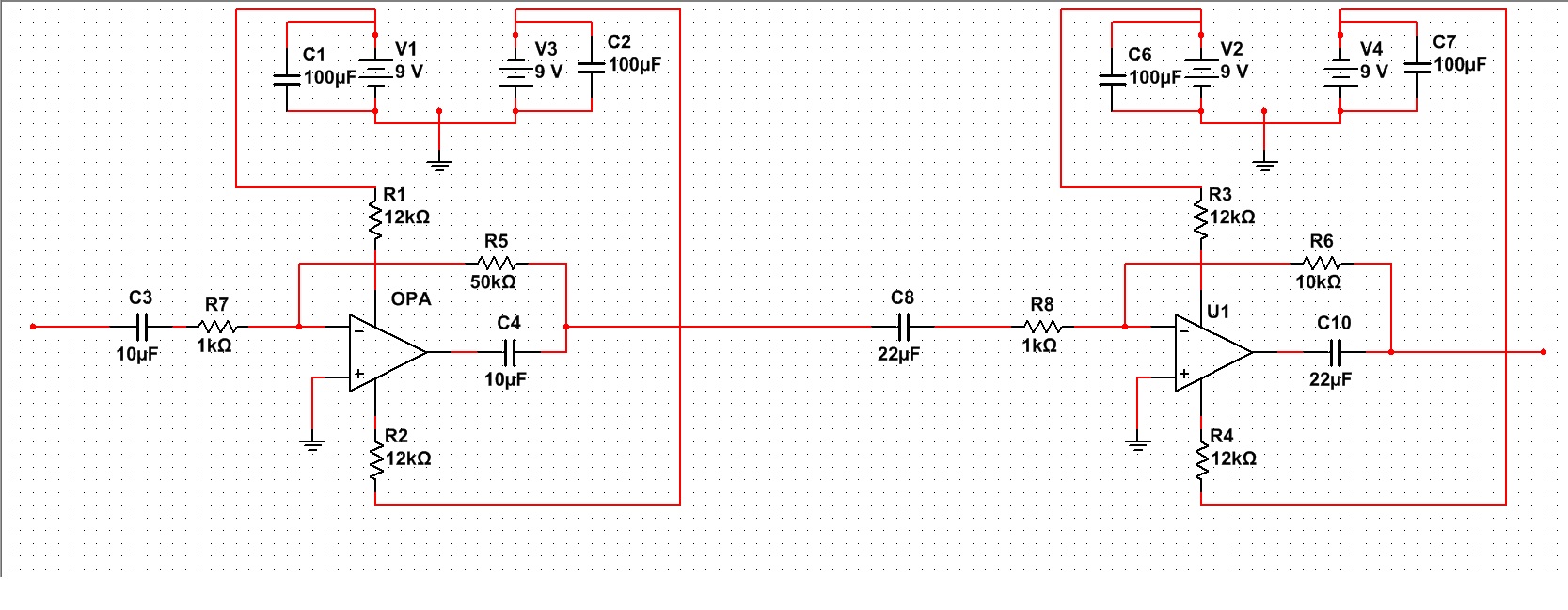
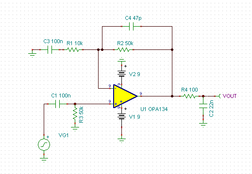
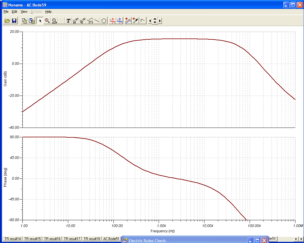
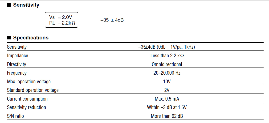
I'm not sure if I'm posting in the right section, so let me know if I have to move this to somewhere else! I need help with OPA 2314. I'm trying to design a preamp for Knowles mics ( NR23158). I've been using LF347 the results is acceptable. I'm trying to use OPA 2314 now, but I'm getting a very high oscillation from the circuit with the gain of 50. Basically, even if I don't connect my mic to the circuit there's this constant noise in the circuit. The bypass capacitor helped but it's still not acceptable. I'm pretty sure there's something I'm missing. There should be a difference between LF347 and OPA 2314. I checked the datasheet and they seems to have an almost same characteristics for my preamp. Also, does it matter if I used like 50k and 1k to get the gain of 50 and maybe 500 and 10 ohms to get the same gain? Should I use different values for my capacitor and resistor? I don't think 50 gain is too high, where is this Oscillation coming from. I'm very new to this, I'd really appreciate it if someone can help me out here.

Thanks!

Ramin

  • Hi Ramin,

    There are many posts on this forum already devoted to microphone / geophone / hydrophone applications, please search through the forum for research.  Here is such a post:

    http://e2e.ti.com/support/amplifiers/precision_amplifiers/f/14/t/161153.aspx

    Also a few years back we published an article on electret condenser microphones and I believe we actually used a Knowles model for the specifications and testing.

    http://www.en-genius.net/site/zones/audiovideoZONE/technical_notes/avt_030110

    Regarding the stability concerns, you are likely either driving a capacitive load (intentionally or not) or have developed a delay in the circuit due to the feedback resistor and the input capacitance of the amplifier combined with any PCB parasitic capacitance at the inverting input (summing node).  My colleague, Bruce Trump, has recently authored a few blogs about OPA stability which are a great read, see below:

    http://e2e.ti.com/blogs_/b/thesignal/archive/2012/05/23/why-op-amps-oscillate-an-intuitive-look-at-two-frequent-causes.aspx

    http://e2e.ti.com/blogs_/b/thesignal/archive/2012/05/30/taming-the-oscillating-op-amp.aspx

    http://e2e.ti.com/blogs_/b/thesignal/archive/2012/06/05/taming-oscillations-the-capacitive-load-problem.aspx

    Otherwise, please attach a full schematic of your circuit and we can take a look. 

    Regards,
    Collin Wells
    Precision Linear Applications

  • Hi Collin, 

    Thanks for a quick response. I will check those links out. Meanwhile I have attached the schematic for my circuit.  I need to have a cut off frequency of around 100 to 200Hz in the input HPF and I might add a capacitor in parallel with the feedback resistor to cut the high frequency noise around 25KHz. The thing is that OPA is oscillating even without the microphone and I need to get rid of that oscillation before I move on to those parts. At the same time I need to figure out how to use the preamps built in the Knowles mics, I'll check your article on the testing. I want to get a low noise output from microphone with a reasonable high amplitude. I would appreciate any comments you may have on how to improve the design.

    Thanks,

    Regards,

    Ramin

  • It's OPA 2134 not 2314 my bad!

  • okay, I went through the links, here is my new schematics. I'm nothing getting any signal out from the op-amp but I can see the oscillation. C3 is 10uf not 22uf. 

  • Hi Ramin,

    Your current topology is not correct and needs to be changed.  I know you mentioned that you were building a microphone system, so what are your goals for gain and filtering in this circuit?  In the mean time, please try the circuit below, it is much more standard and easy to implement:


    8054.Simple Microphone Circuit.TSC

    You can view / modify / edit the attached circuit in TINA-TI a free simulator offered by TI at the following link: 

    http://www.ti.com/tool/tina-ti

    Regards,
    Collin Wells
    Precision Linear Applications

  • Hi Collin, 

    Thanks again! The reason my circuit looks like this was because I was trying to get rid of the oscillation using the schematic in, (figure 2)

    http://e2e.ti.com/blogs_/b/thesignal/archive/2012/05/30/taming-the-oscillating-op-amp.aspx

    I also have added the bypass capacitors to my design. I will examine your design and let you know how it work out. I'm still not sure what gain I might be using for op amp, I would like to be able to record a speech signal using the microphone and the preamp from 3 to 5 feet away from the microphone and be able to hear it back in a reasonable volume. Do you know by any chance what is the highest gain I can get out of this opamp? For the filters, I'd basically want to have the human audible rang from 20Hz to 20KHz but the values don't have to be exact, so probably something around 100 or 200 Hz to 25KHz would work too. 

    If it's possible can you explain a little about how your design works and why you choose the resistors and the capacitors in that configuration and why those specific values? 

    Also, you used the non inverting input, why didn't you use the inverting input ? I'm not sure what difference they'd made in my design. 

    And one more question, do you think bypass capacitors and using a regulator would help to take the ripples off from the power supply? 

    It's awesome that TI has a free simulator, I'll definitely give it a try! YOU GUYS ARE AMAZING!

    Best,

    Ramin

  • Hi Ramin,

    Bypass capacitors are always required for proper operation of precision circuits.  Be sure to place them as close as possible to the supply pins of the OPA for the highest effectiveness.  Using a linear regulator (LDO) to clean up your power supply is also a common design practice to clean up a dirty supply.

    I used the non-inverting input so you would get a non-inverted output.  Your first circuit used two inverting amplifiers so the final output was non-inverted and your second circuit was non-inverting so I figured you wanted non-inverting.  I believe non-inverting would be desired in your application. 

    Your goals happen to be very close to the goals of the final circuit in the article I posted to the first post.  Please read through the article in full.  It describes how to estimate the approximate voltage output of your microphone for different Sound Pressure Level (SPL) inputs.  You can then determine what SPL input the human voice corresponds to at 3-5ft for a loud vs. quiet voice and then set the gain of your circuit appropriately so you can still acquire the low-level signals without clipping a loud signal.

    http://www.en-genius.net/site/zones/audiovideoZONE/technical_notes/avt_030110

    I fielded may questions on this design in the following post so look there for more information about the design:

    http://e2e.ti.com/support/amplifiers/precision_amplifiers/f/14/p/113888/403584.aspx#403584

    Regards,
    Collin Wells
    Precision Linear Applications

  • Dear Collin, 

    Great paper, it's very similar to what I'm trying to do. Do you have any suggestions on the value of bypass capacitor? 

    Where can I get that microphone model you used in your paper in TINA TI? And how can I add a wav. file to the simulator as an input? Do you have any suggestions on the type of the capacitors? 

    The Knowles microphone that I'm using have a frequency response between 100Hz to 10KHz so I don't need to be exact on 20Hz and 20KHz. One main problem is the phase change; I need to have a constant (  0 degree is preferred) phase between 100Hz to 10KHz and at the same time I need a high gain. 

  • About the inverting pins, what is the difference between inverting the input two times or only using the non inverting inputs? I tried in TINA and for some reasons the non inverting has high amplitudes in noise. 

    What's the purpose of that 33pf capacitor between the two inputs in the paper you sent me? 

    Why did you say that the highpass filter is a second order? and if it's a second order why did you include one resistor and capacitor to find the cut off freq? 

    How do you add noise to the model you have in TINA and how do you know what kind of noise you have to use? 

    what is the purpose of that capacitor in the output of the op amp that's grounded? I used a coupling capacitor for my previous design but that doesn't seem to be a coupling capacitor or is it ?!

    I looked up the datasheet for the microphone you used for the testing, it's from almost 50Hz to 17KHz how did you managed to get 20 to 20KHz? 

    You mentioned a rule of thumb on being 25% below/above for HP/LP freq, where did you get that number? What is it called in the datasheet? 

    Before I had a problem with a four LF347. I'm recording the sound from 4 different microphones and I need all of them to have a same phase vs freq so I have to use the same circuit with the same gain for all of them. The problem is that there's a bleeding from one channel to the other channel and I'm loosing an almost 30% of each signal, and it's very important for me that this is reduced to the min amount. How can I do this? Would it help to use a one or 2 input opamp? and if yes, would that affect the noise level on the signal? 

    Thanks a lot for helping me out, I'd really appreciate your help!

    Cheers!

    Ramin

  • Ramin,

    There are too many questions here that are answered in the article and the following link that I asked you to read as well. 

    http://e2e.ti.com/support/amplifiers/precision_amplifiers/f/14/p/113888/403584.aspx#403584

    Here is the TINA model file with the microphone model included, I don't know how to import a .WAV file.  You should try testing with discrete signals first as described in the article. 

    8306.Full Circuit OPA134.TSC

    I pulled up the datasheet for the WM-61A microphone and here are the specs, it states 20-20kHz:

    Designing the noise source is explained in detail in the paper in the "Modelling SNR" section of the paper.

    I don't see a capacitor "in the output of the amplifier that's grounded" not sure what you're referring to. 

    The 25% is a simple rule of thumb I came up with some years ago.  If you want a semi flat response (-0.25dB) at a particular frequency then set the pole/zero 4-times greater/less than the desired cutoff frequency.  Remember that the actual cutoff frequency (1/2*pi*R*C) is the -3dB frequency which is already quite attenuated.  The "Modelling Frequency Response" section covers this in detail:

    Regarding your previous troubles with the LF347, perhaps you didn't have proper supply decoupling or your layout allowed for capacitive coupling which was causing the signals to affect each other. 

     Regards,
    Collin Wells


  • Thanks Collin, I will read more carefully and come back with more questions!

    I mean the capacitor (2,22pf) on the circuit that you suggested on this post, the one in the output of the opamp, What's that for?

    Thanks again for your help!

    Regards,

    Ramin

  • Hi Ramin,

    That capacitor in combination with the resistor in series with the output forms a low-pass filter with cutoff = 1/(2*pi*R*C), it could be useful to attenuate out higher frequency noise signals.

    Regards,
    Collin Wells

  • Hi Collin, 

    Could you please take a look at the following circuit. For some reasons I'm getting a very high oscillation in my output. It seems drop if I disconnect the voltage dividers from the non inverting inputs, but of course the amplitude drops too. 

    Also, How can I connect the coupling/decoupling capacitor in this circuit for the microphone and the output of the opamp?  

    1401.opa newest.TSC

    Thanks,

    Regards,

    Ramin

  • I just wanted to give some more info here, even if I don't connect the input signal oscillation is there. I tried different values for the voltage divider, oscillation is still there. The output from the first stage with out connecting it to the second stage is also oscillatated. 

  • Hi Ramin,

    Your circuit looks okay, I'm surprised it oscillates.  However the OPA140 is not an appropriate choice for a +5V application because of the limited input range in this configuration.  With a +5V supply, the input range is only 0.1V - 1.5V as stated in the input common-mode voltage range spec.  Let's close out this thread and move the rest of the conversation to the post where you specified your design requirements.  I'll put together a circuit with the OPA376 that you should hopefully be able to modify the rest of the way to your needs.

    Regards,
    Collin Wells

  • Hi Ramin,

    I realized that you actually had the OPA134 in the circuit not the OPA140.  The OPA134 has a swing of (V- +2.5) - (V+ -2.5V) so with V- = 0V and V+ =5V you basically have no usable input range. 

    I'll continue on the other thread as mentioned before.

    Regards,
    Collin

  • Hi Collins, 

    I figured that the microphone I've been using doesn't have a good flat freq response and not a good 8 figure so I need to use NR23158 knowles microphone Please find the link for the datasheet. http://www.knowles.com/search/prods_pdf/NR-23158-000.pdf

    This microphone is not working with the current design of the OPA2317, any suggestions? 

    Thanks,

    Regards,

    Ramin

  • I have another question, this knowles mic has a high impedance how does that affect my choice of the opamp? I used INA217 before and it didn't work, the IC gets too hot. 

  • Hi Ramin,

    The INA217 won't get hot unless you've connected something improperly.   Regarding your previous question, I assume you mean the OPA314 not OPA317.  The circuit I provided using the recommended OPA376 which is a low-noise OPA should also work with the OPA314 although the results may not be as good.

    Regarding the voltage dividers:  if you look at the circuits, when you connect the same voltage divider to both places you're effectively shorting out the first OPA because the positive input of both amplifiers get tied to the same net and the input signal likely finds some strange path around the first amp causing issues with the second.  It wouldn't be an issue if we weren't building a non-inverting system where the input signal is summed with the common-mode voltage at the non-inverting input.  But since this system is non-inverting we need two dividers.

    Regards,
    Collin Wells

  • Hi Collin 

    I see your point, that's gonna be a lot of voltage dividers then. I think positive and negative supply would be a better choice since I have to amplify four different inputs at the same time. 

    Thanks.

    Regards

    Ramin