This thread has been locked.

If you have a related question, please click the "Ask a related question" button in the top right corner. The newly created question will be automatically linked to this question.

Bubba oscillator with TLV2474

Other Parts Discussed in Thread: TLV2474, TINA-TI

Greetings!  My name is Gilberto and i am a graduation studdent of automation engineering from Brazil. I am having trouble with the understanding of the function and sizing of the resistors Rg and Rf for the bubba oscillator circuit described on the application report SLOA060 - march 2011, page 17 figure 18. The oscillator porpuse is to develope a current inverter thru the H-bridge topology, oscillating on a frequency of 60Hz. The RC filter i've calculated from the equation 'f=(1/(2*pi*R*Cs))' in order to oscillate on this particular frequency is built up by either a 26,5kOhm resistor and 100nF capacitor or a 3,9kOhm resistor and 680nF capacitor, for all four RC filters. The op amp i am going to use for this circuit is the same presented by the application note, TLV2474. I'd apreciate very much if you could help me with this and even tell me if this circuit is able to fulfill the task. Thank you very much in advance!!

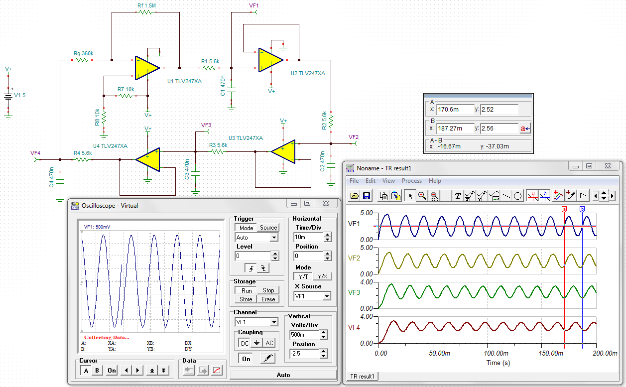
I tried to simulate it on TINA-TI and failed, below is the circuit schematic i designed:

6472.bubba osc example.TSC

And the transient simulation result:


  • Hello Gilberto,

    Getting an oscillator to start up in a PSpice simulator can sometimes be a little tricky because the simulation circuit sometimes need a bit of push or the right start-up conditions to get it going. However, TINA-TI is usually pretty good about doing so - at least from my experience. The way to get the Bubba oscillator started for this case is to select the Analysis tab, and Transient. Then, when the Transient Analysis window appears, move the bullet selection from Calculate operating point, to either Use initial conditions, or Zero initial values. Once the simulation is completed the transient analysis should display the oscillation at the designated measurement points. You can see the results I obtained:

    The markers indicate a per cycle time of 16.85 ms, for a frequency of 59.3 Hz. Not too far off of 60 Hz for standard 5 % component values!

    The point of oscillation in the Bubba occurs when the phase shift of each of the four stages is -45 degrees. The unadjusted gain at -45 degrees phase shift is -3 dB, or 0.707 V/V. If each stage has a gain of 0.707 V/V, then the overall gain would be (0.707)4 or 0.25 V/V. Therefore, for oscillation to occur a gain of >= 4 V/V must be applied within the loop to attain an overall gain of 1 V/V. Since 4 x (-45 degrees) only accounts for -180 degrees having one stage operating as an inverter results in 0 degrees of total phase shift between the input and output (positive feedback). Thus, with a gain of 1 V/V (or slightly more) and a phase shift around the loop of 0 degrees the Barkhausen criterion for sustained oscillation is satisfied. See en.wikipedia.org/wiki/Barkhausen_stability_criterion

    I hope this helps get you started.

    Regards, Thomas

    PA - Linear Applications Engineering

  • Hello Thomas,

    Thank you very much for your support, it was very helpful! As you can see on the picture, i changed the values of the RC filters in order to adjust the frequency to the closest possible of 60hz. With 5,6kOhm resitors of 1% tolerance and 0.47uF capacitors of 5% tolerance, the cycle time is 16,67ms, and the frequency is then 59,988Hz. Although i has been able to make the circuit oscillate with the same resistor values for Rg and Rf (360kOhm and 1.5MOhm, respectively), i still dont understand the relationship these two components have with the gain and amplitude of the circuit.

    The information you have provided me is enough for making the circuit to function, but it would be quite a great help if you could elaborate on the role these resistors have on this oscillator circuit.

    In any case, i am sincerely grateful for the support you gave me!

    Gilberto

  • Hi Gilberto,

    I mentioned in my previous response that a gain of at least 4 V/V had to be included in the circuit to over come 0.707 V/V voltage gain of each stage at the -45 degree phase frequency. The gain of the overall circuit would be the product of each of the 4 stages, (0.707)4 or 0.25 V/V. Including a gain stage with a gain of 4 V/V results in an overall gain of 1 V/V around the loop. A gain slightly larger than 1 V/V helps assure oscillation.

    The 1.5 Meg feedback resistor (Rf ) and 360 k input resistor (Rg) connected to U1 set up that TLV2474 amplifier stage to operate with a gain of approximately -4.17 V/V (minus sign indicates inversion). A Gain of 4.17 V/V is high enough to assure the circuit will oscillate, but not so high as to cause the circuit to be over driven and cause clipping.

    Regards, Thomas

    PA - Linear Applications Engineering

  • Thank you again, i believe i've understood it now. :)