This thread has been locked.

If you have a related question, please click the "Ask a related question" button in the top right corner. The newly created question will be automatically linked to this question.

Not able to access EMIF2 : DDR3L

Other Parts Discussed in Thread: X5777BXGABC

Hi

We are using X5777BXGABC processor in one of our design.Where I'm not able to access DDR3L chips(1GB) which has connected to the EMIF2 controller.

I tried connecting JTAG with reduced clock but not able to access any of the DDR registers.

One thing i could observe by probing is that CKE of EMIF2 is not toggling.Its idle  as high(Vtt).

Can any one help me further debugging this issue.

  • Hi Anand,

    I have forwarded your question to EMIF experts to help.
    Meanwhile you can check if you can find something useful in this document:
    www.ti.com/.../sprac36.pdf

    Regards,
    Yordan
  • Hi Anand,

    Please check if the CTRL_CORE_SMA_SW_0[1] EMIF2_CKE_GATING_CTRL bit is cleared. If set to 0x1, EMIF2 can't take control over CKE.
    I assume everything is fine with EMIF1. If you also have 1GB connected to EMIF1, you can use the same register settings for EMIF2. The only difference is that EMIF2 doesn't support ECC.

    Another thing to check are the DMM_LISA_MAP_i, the CTRL_WKUP_SECURE_EMIF2_SDRAM_CONFIG and CTRL_WKUP_EMIF2_SDRAM_CONFIG_EXT registers.

    BR,
    Dobrin
  • Dear Dobrin,

    Thanks for the reply,

    I have tried reading the register CTRL_CORE_SMA_SW_0
    EMIF2_CKE_GATING_CTRL bit set 0x0.So its clear that CKE pad controlled by processor.

    Your assumption is correct ,I do have DDR3L chips connected to EMIF1 controller and its working fine.The same registers setting i used for EMIF2 but there is no improvements.

    One more observation,I have connected JTAG debugger with configuration setting only EMIF2.I'm able to write on some of the DDR address locations but the data on adjacent locations also getting affected.
  • Anand,

    Have you also checked the control module registers? The CTRL_WKUP_SECURE_EMIF2_SDRAM_CONFIG register exports its values to EMIF2.EMIF_SDRAM_CONFIG register at POR. CTRL_WKUP_SECURE_EMIF2_SDRAM_CONFIG should have same settings as CTRL_WKUP_SECURE_EMIF1_SDRAM_CONFIG register. These registers are used to specify important EMIF parameters.

    The CTRL_WKUP_EMIF2_SDRAM_CONFIG_EXT register should also have same values as CTRL_WKUP_EMIF1_SDRAM_CONFIG_EXT (assuming you don't use ECC, otherwise ECC must be enabled in CTRL_WKUP_EMIF1_SDRAM_CONFIG_EXT).

    The DMM_LISA_MAP_i registers are also important. They control the interleaving between EMIF1 and EMIF2, address mapping and other important parameters. There are also registers that control the output impedance, slew rate and weak pull resistors of the DDR IO cells. These regs are: CTRL_CORE_CONTROL_DDRCACH1_0, CTRL_CORE_CONTROL_DDRCH1_0, CTRL_CORE_CONTROL_DDRCH1_1, CTRL_CORE_CONTROL_DDRCH1_2 for EMIF1 and CTRL_CORE_CONTROL_DDRCACH2_0, CTRL_CORE_CONTROL_DDRCH2_0, CTRL_CORE_CONTROL_DDRCH2_1 for EMIF2.

    In addition, when you use JTAG, do you use CCS and default gel files? The EMIF gel file performs all required steps to initialize both EMIFs.

    One more question, I assume your board is designed using fly-by topology and leveling, right?

    BR,
    Dobrin
  • Dobrin,

    I have checked all the registers parameters values as you mentioned earlier for EMIF1 and EMIF2.
    We observed that the values are same for the both EMIF's registers as we are configuring from the Uboot code.

    Also we tried with the available gel file (/opt/ti/ccv5/ccs_base/emullation/gel/DRAxx/DRA7xx_ddr_config.gel) with the modified value in lisa_map register. We are not able to access the EMIF2 memory controller's DDR.

    We thought to debug from the hardware side and we have observed that CKE is not toggling for EMIF2 controller and the signal is always high.


    Regards
    Anand
  • Anand,

    I also thought about HW issue but first wanted to confirm everything is OK from SW side.

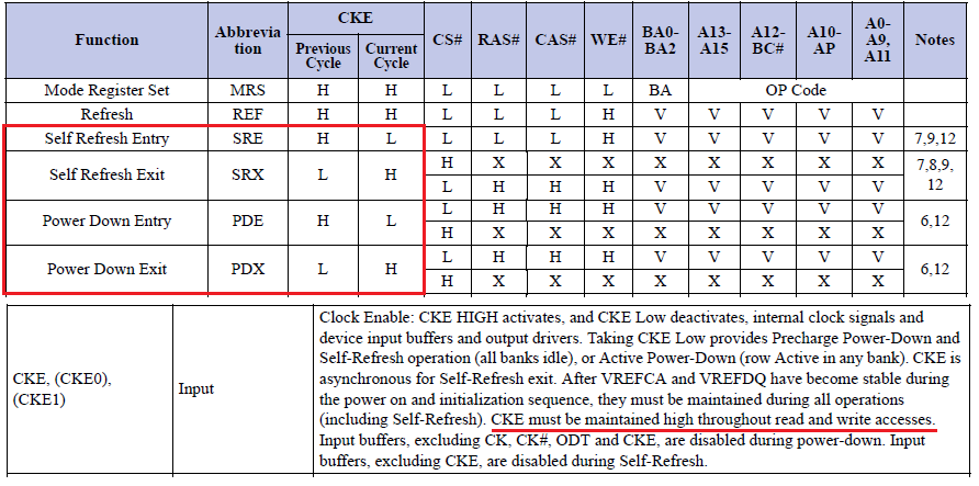
    High level of CKE is normal. According to DDR3 JEDEC spec (JESD79-3F) CKE is low only during Self Refresh and Power Down commands. It must be high during reads and writes. Here is an excerpt:

    Could you please send the LISA_MAP_i register settings just to verify everything is OK?

    BR,

    Dobrin

  • Hi Dobrin,

    Please find below LISA_MAP_i register settings that we have configured for 1.5GB.

    .dmm_lisa_map_0 = 0x0

    .dmm_lisa_map_1 = 0x80640300

    .dmm_lisa_map_2 = 0xc0500220

    .dmm_lisa_map_3 = 0xff020100

    I have one more doubt regarding CKE signal voltage level.The Vih(min) level should be more than Vref correct?
    In our scenario its exactly VDDQ/2.
  • Anand,

    Sorry for the late reply… According to the J6 data manual Voh min of CKE is 0,9*VDDS, and VREF is 0,5*VDDS. Obviously, Voh min of CKE must be more than VREF. Have you compared EMIF1 CKE and EMIF2 CKE?

    The LISA_MAP settings seem to be OK. You have 1,5GB configuration. 1GB interleaved between EMIF1 and EMIF2 with 256b granularity and 512MB mapped only to EMIF1.

    BR,
    Dobrin
  • Dobrin,

    Yes I have compared CKE of working EMIF1 and Its toggling during initialization stage(going low then high) but same thing not happening on other EMIF2 CKE signal.

    So, testing purpose I have shorted CKE of EMIF1 to EMIF2 CKE and my board booted successfully.I tried with both 1.5GB and 2GB configuration and Its working fine.

    I would like to know whether this approach is fine ?

    Regards
    Anand
  • Anand,

    It seems to be a HW issue with EMIF2 CKE. Have you measured the termination resistor between CKE and VTT? It should have same value as the one for EMIF1. Do you have pull down connected to CKE? Please check.

    It's not a good approach to short EMIF1 and EMIF2 CKE signals. IMO, the board has booted successfully not because you have connected EMIF2 CKE to EMIF1 CKE but because you have connected it to a valid voltage level. If you had connected EMIF2 CKE to another valid voltage level that remains high, you shall also have booted successfully. As I previously said, CKE is low only during Self Refresh and Power Down commands.

    Please check the resistor values as I mentioned above.

    BR,
    Dobrin
  • Dobrin,

    We have 47E termination resistors for both the CKE signals(both measured as 46.5E) and I do have 4.7k pull down resistors for same.

    Yes, Its the HW issue wrt EMIF2 CKE line as there may be a chance of contact issue (b/w ball & pad or via breakage) that i need to figure it out.

    1. Then can i short CKE of EMIF2 to VDDQ (Valid high)with termination resistor ?
    2. In this approach what about CKE of EMIF1 since we are using interleaving b/w EMIF's. Do i also need to isolate this pin and give always high(VDDQ).
    3. what are the effects of not having Self-refresh operation on my DDR chips? Basically self-refresh operation deactivates the clock to reduce the power consumption of the device and it automatically executes a refresh operation by using the internal refresh counter.


    Regards
    Anand
  • Anand,

    Sorry for the late reply. I was OoO.

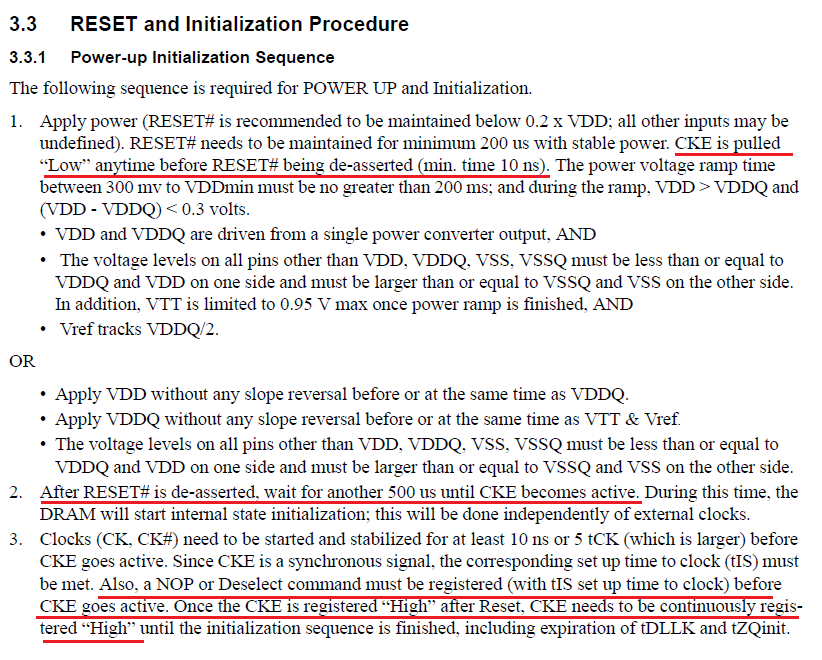
    1. I don't think shorting CKE to VDDQ will always work although VDDQ has valid voltage level. According to the JEDEC DDR3 spec CKE must be pulled low on power-up.
    Then, after RESET# de-assertion you should wait for 500us until CKE becomes active. This is mentioned in section "3.3 RESET and Initialization Procedure" of the JEDEC DDR3 spec.
    Here is an excerpt:


    I cannot comment what will happen if you simply connect CKE to VDDQ. If you have luck SDRAM might be accessed successfully.
    If your board is for evaluation purpose, you may use your current "HW patch" but I do not recommend to use it in a final product.
    Such workarounds are OK for testing purpose or if you need to fix something without producing new board but must not be used in a product intended for customer use.
    Anything else other than connecting EMIF2 CKE to SDRAM CKE pin is not a good and professional engineering approach. Sorry if it sounds a bit rude. That wasn't the intent.
    In addition, the J6 Data Manual also states that CKE is low after power-up.

    2. If you find a way to follow JEDEC without using EMIF2 CKE I don't think you also should isolate EMIF1 CKE. This shouldn't impact interleaving.

    3. If you don't use self-refresh, power consumption will be higher but I don't expect significant difference. Please note that in this case the EMIF_POWER_MANAGEMENT_CONTROL[10:8] LP_MODE bit field should be set to value != 0x2 to disable self-refresh.
    Another impact of not using self-refresh is that you won't be able to change the EMIF_FICLK frequency as it can be changed only after putting the external SDRAM in self-refresh mode.

    BR,
    Dobrin

  • Hi Dobrin,

    Thanks for your valuable suggestions in debugging this DDR issue.

    I appreciate your concern,we are using this board for internal evaluation purpose and not for customer use.