This thread has been locked.

If you have a related question, please click the "Ask a related question" button in the top right corner. The newly created question will be automatically linked to this question.

ADS1018: ADS1018 Communication issue

Part Number: ADS1018

Hello,

I have a communication issue with ADS1018. The symptom is the DOUT data is not the same with DIN data on CONFIG MSB& CONFIG LSB when using 32-bit data transmission cycle. Here is DIN data: 0x05,0x8b,0x05,0x8b, but DOUT data: 0x80,0x00,0x05,0x89.

Could anyone suggest the possible cause?

Here is schematic.

  • Paul,


    With the bits [2:1] in the configuration register reading back 00b, I think that the device is not correctly receiving the data. There are a few things that I would check.

    Start by checking that the SPI is the correct mode. Data is clocked into the device with the falling edge of the SCLK and the clock idles low. Check that the SCLK rate isn't going to fast. This device limits SCLK to 4MHz. I'd also look through the timing diagrams and check to see that all the remaining timing is correct (page 8 of the datasheet).

    One other important thing to check would be the physical communication. I would use an oscilloscope or logic analyzer and look at the /CS, DIN, DOUT, and SCLK lines coming in and out of the device just to see that they are well behaved. Because you have a digital isolator, I would look at both sides of the isolation just to see that they are the same. However, I would focus on the device side, checking to see that the communication going is what you expect. If you continue to have problems, post the SPI communications from the scope back to this thread and we can look over them. I'd like to see enough detail to be able to read the waveforms.


    Joseph Wu

  • Hi Joseph,

    Customer has tried to bypass the isolator and the issue still exits.

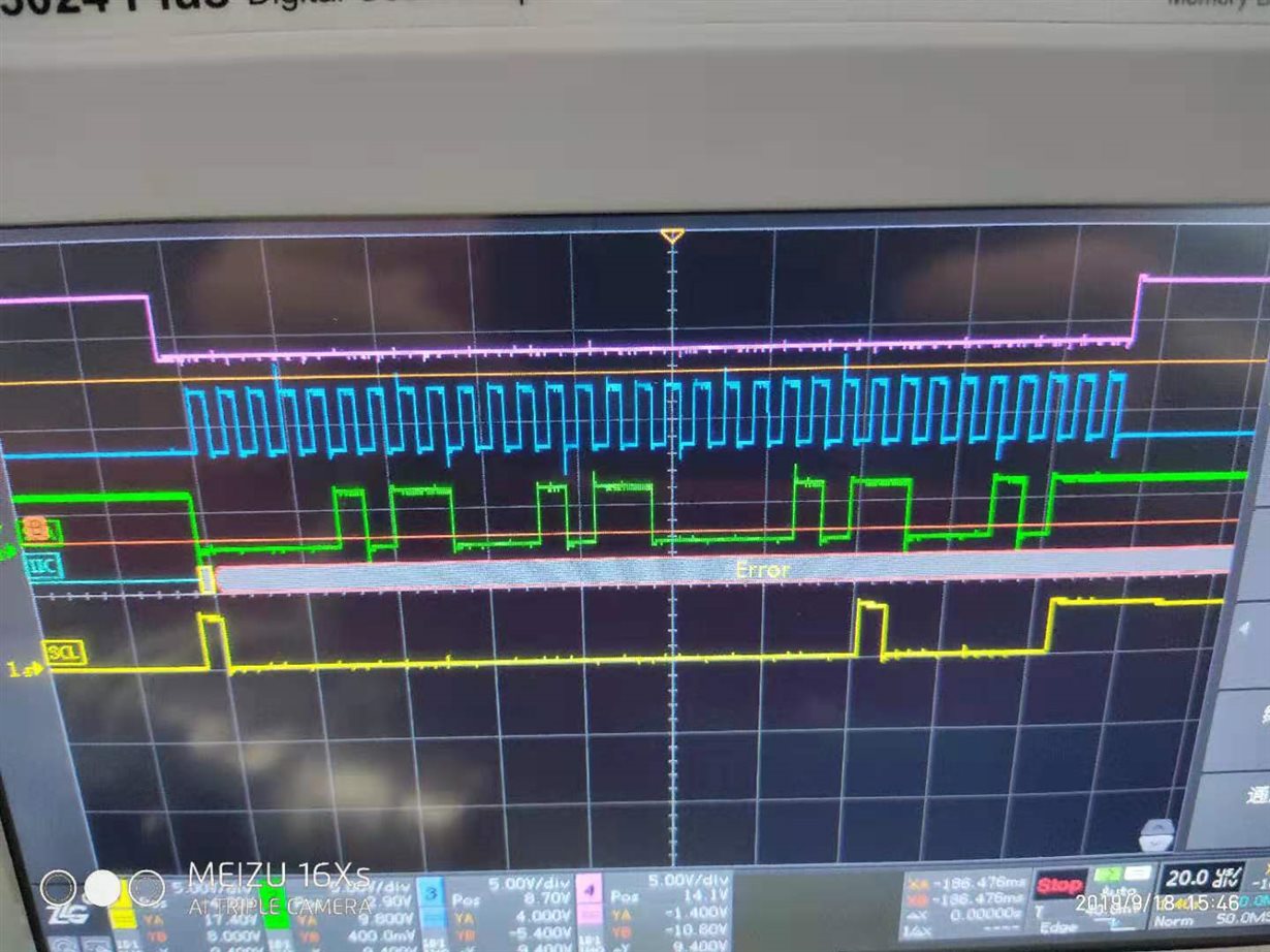
    Here is scope waveform captured by customers:

    Purple: CS; Green: Clock; Blue: DIN; Yellow: DOUT. Write data: 05 8b 05 8b, Read data: 80 00 00 81.


    Do you see any problem from the waveform? Thanks!


    Paul

  • Paul,


    Assuming that DIN is green and SCLK is blue, the customer is using the wrong mode for SPI. Looking at the way that the customer is clocking in data, the DIN is set on the previous falling edge of SCLK and clocked into the device at the rising edge of SCLK.

    However, the ADS1018 uses a different mode of SPI. DIN should be set up on the rising edge of the SCLK and clocked into the device at the falling edge of SCLK. When reading back data from the device, the same mode of SPI is used.

    This should be something set up by the microcontroller used and they'll need to set it up through their programming.


    Joseph Wu