This thread has been locked.

If you have a related question, please click the "Ask a related question" button in the top right corner. The newly created question will be automatically linked to this question.

Connecting ADS1258 to Arduino Mega 2560

Other Parts Discussed in Thread: ADS1258

Hello TI support:

Now I am trying to connect an ADS1258 ADC converter to an Arduino Mega 2560 microcontroller. My goal is to apply a signal to ADS1258, connect ADS1258 to Arduino and Arduino to a computer, and read the time-variant voltage on the computer (the ADS1258 has been tested with MMB0 board as ADS1258-EVM-PDK, and it worked fine). The connection as follow:

Power:
3.3 V (ADC J5.9) to lab power source
5 V (ADC J5.3) to lab power source
GND (ADC J5.5) to lab power source
Signal wires:
A 20 Hz, 2 Vpp sinusoidal signal is applied on A0, A1 (ADC diff0) by a function generator
SCLK(ADC J6.3, input) to SLK(controller 52, output)
CS(ADC J6.7, input) to SS(controller 53, output)
DIN(ADC J6.11, input) to MOSI(controller 51, output)
DOUT(ADC J6.13, output) to MISO(controller 50, input)
DRDY(ADC J6.15, output) to INT(controller 2, input)
USB cable:
Arduino to computer
All ADC converter configuration setting is default. My arduino code as follow:

#include <SPI.h>
const int DRDY=2;
const int DOUT=50;
const int DIN=51;
const int SCLK=52;
const int CS=53;

byte stat,data1,data2,data3;

void setup (void)
{
  Serial.begin(9600);
  pinMode(DRDY,INPUT);
  pinMode(DOUT,INPUT);
  pinMode(DIN,OUTPUT);
  pinMode(SCLK,OUTPUT);
  pinMode(CS,OUTPUT);
  SPI.begin();
  digitalWrite(CS,LOW);
  digitalWrite(DIN,LOW);
}

void loop (void)
{
  if (digitalRead(DRDY)==HIGH)
  {
    SPI.transfer(0B00110000);
    stat = SPI.transfer(0x00);
    data1 = SPI.transfer(0x00);
    data2 = SPI.transfer(0x00);
    data3 = SPI.transfer(0x00);
    Serial.println();
    Serial.println(data1, DEC);
    Serial.println(data2, DEC);
    Serial.println(data3, DEC);
  }
}

However, the code only returns some random stuff like:

241
31
157

241
31
157

241
31
157

241
31
157

Here are my questions:

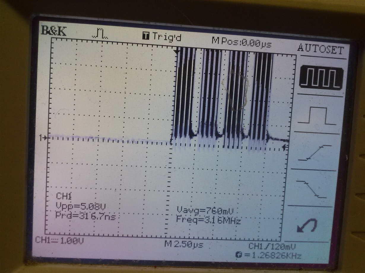
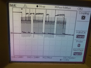
First, what are the timings to read data from DOUT? I measured SCLK on oscilloscope, and found that there are 4 packages of pulses (8 pulses each), which correspond to a 4-byte data reading period. The frequency of pulses in each package is about 4 MHz. However, I also need to know the correct delay to read data between packages and data reading periods, and add them into my code using delay() command. How should I get those timings correctly (and, according to my experience using ADS1258-EVM-PDK, the sampling rate is related to the number of channel being used)?

Second, after I get the timing correct, I can only get one bit data for diff0 channel in one 4-byte data reading period. However, to represent a voltage signal, I need a 24-bit voltage reading code (-8388608~8388607 as in ADS1258-EVM-PDK) from at least 24 4-byte data reading period. So, how should I assemble such a voltage-reading code?

Also, I cannot see where DRDY is low during the test. Maybe the low-phase is too short so I cannot see it on the oscilloscope, or is there something wrong with my connecting or setting on it? 

By the way, I refered to the post when connecting my boards: http://e2e.ti.com/support/data_converters/precision_data_converters/f/73/p/172252/640668, but it does not contain much code or explain my questions. Sorry I am relatively new to ADC converter and microcontroller...

Thank you!

Xing

  • Hi Xing,

    Welcome to the TI E2E Forums!

    Since you are jumper wiring to the ADS1258EVM, you may want to double check the connection requirements posted here:

    To answer your questions:

    Xing Wang said:
    First, what are the timings to read data from DOUT? I measured SCLK on oscilloscope, and found that there are 4 packages of pulses (8 pulses each), which correspond to a 4-byte data reading period. The frequency of pulses in each package is about 4 MHz. However, I also need to know the correct delay to read data between packages and data reading periods, and add them into my code using delay() command. How should I get those timings correctly (and, according to my experience using ADS1258-EVM-PDK, the sampling rate is related to the number of channel being used)?

    Timing requirements for reading data are shown in Figure 1 and Table 1 on page 7 of the ADS1258 datasheet. Any command specific timing will be given in the Command Description section of the datasheet (pages 31-35). For reading data, are you using read direct mode or read by command mode?

    For timing delay from start to /DRDY low, refer to table 11. You should also pay attention to the Settling Time section. For the most part, you will want to use a /DRDY falling edge interrupt to signal when to read data. The main exception is the settling time that may require you to ignore the first five interrupts.

    From your code it looks like you are waiting for /DRDY to go HIGH:

    if (digitalRead(DRDY)==HIGH)

    During this time data is invalid, which may be the read you see random readings.

    Xing Wang said:
    Second, after I get the timing correct, I can only get one bit data for diff0 channel in one 4-byte data reading period. However, to represent a voltage signal, I need a 24-bit voltage reading code (-8388608~8388607 as in ADS1258-EVM-PDK) from at least 24 4-byte data reading period. So, how should I assemble such a voltage-reading code?

    I'm a bit confused...have you gotten the timing correct? You should be reading a 2's compliment 24-bit output code in 3 packages of 8-bits. Once you've read the code, combine the bytes, sign extend the number to fit the data type, and then multiple the signed number by the ADC's LSb size (given in Table 10).

    Xing Wang said:
    Also, I cannot see where DRDY is low during the test. Maybe the low-phase is too short so I cannot see it on the oscilloscope, or is there something wrong with my connecting or setting on it? 

    After a conversion completes /DRDY will stay low until you start reading data (as shown in figure 52) or until the next conversion completes (figure 2). Therefore, it should be easy to see /DRDY while it's low.

    Try sending a START command or setting the START pin HIGH to begin a conversion.


    Best Regards,
    Chris

  • Hi Chris:

    OK now I understand the way to assemble the data and how to use the DRDY, but my problem is not solved yet. I keep the wire-up unchanged and revise the code as follow (trying to use read direct mode with auto scan):

    #include <SPI.h>
    const int DRDY=2;
    const int DOUT=50;
    const int DIN=51;
    const int SCLK=52;
    const int CS=53;

    byte stat,data1,data2,data3;
    float dataF;

    void setup (void)
    {
      Serial.begin(9600);
      pinMode(DRDY,INPUT);
      pinMode(DOUT,INPUT);
      pinMode(DIN,OUTPUT);
      pinMode(SCLK,OUTPUT);
      pinMode(CS,OUTPUT);
      SPI.begin();
      digitalWrite(CS,LOW);
      digitalWrite(DIN,LOW);
    }

    void loop (void)
    {
      digitalWrite(DIN,LOW);
      if (digitalRead(DRDY)=LOW)
      {
        delayMicroseconds(30);
        stat = SPI.transfer(0x00);
        data1 = SPI.transfer(0x00);
        data2 = SPI.transfer(0x00);
        data3 = SPI.transfer(0x00);
        dataF=data1*pow(2,16)+data2*pow(2,8)+data3;
        Serial.println();
        Serial.println(data1, DEC);
        Serial.println(data2, DEC);
        Serial.println(data3, DEC);
        Serial.println(dataF, DEC);
      }
    }

    However, two problems show up. First, my DRDY is always high during the whole test, so the Arduino never start to reading. It seems the data is never ready, even if I empty everything in the void loop(). I think this is the major reason that the system does not work. Could you clarify how to wire the START pin and program it?

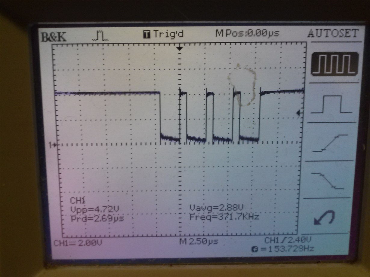
    Second, my DIN does not stay LOW, even if I set it low in void setup() and void loop(). The data sheet said that it must stay inactive to work in  read direct mode, so why is that happen and does it matter?

    Here are some plots of my signals. Hope that may helps:

    SLCK:

    DIN (does not stay LOW):

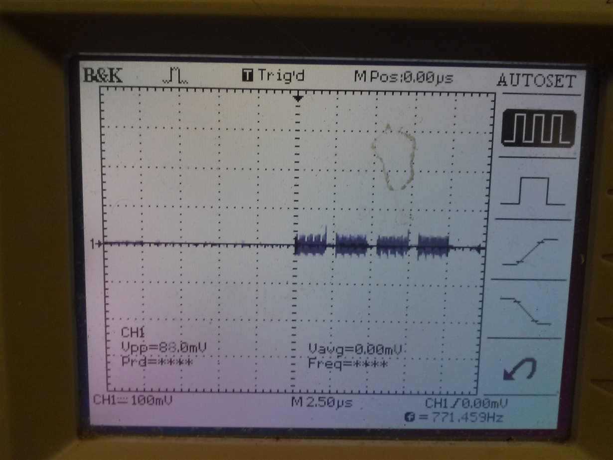
    DOUT (abnormal):

    Thank you for helping me!

  • Hi Xing,

    Do you see any response from the ADS1258 on the DOUT pin, or is it always low? From your oscilloscope screenshot, all I see is the SCLK noise coupling onto the DOUT signal.

    Do you have a ground wire connection between your Arduino and the ADS1258EVM? Quite commonly, this connection is missing when the SPI communication is completely non-responsive.

    Xing Wang said:
    However, two problems show up. First, my DRDY is always high during the whole test, so the Arduino never start to reading. It seems the data is never ready, even if I empty everything in the void loop(). I think this is the major reason that the system does not work. Could you clarify how to wire the START pin and program it?

    Look at page 27 of the ADS1258 data sheet. You have the option to use an Arduino GPIO pin to control the ADS1258 START pin. Otherwise, you can send a pulse convert command to begin conversions.
    The start pin is connected to J3.3, and by default, a jumper connects the ADS1258's GPIO0 to START. However, you can remove the jumper and control the START pin directly.


    Xing Wang said:
    Second, my DIN does not stay LOW, even if I set it low in void setup() and void loop(). The data sheet said that it must stay inactive to work in  read direct mode, so why is that happen and does it matter?

    You should be in control of DIN's behavior by how you program it! Do you have a pull-up resistor on your Arduino board, or can you configure it to be active low?

    It looks like you're just missing a simple connection somewhere! Try probing your power supplies and check the logic level on the ADS1258's /PWDN pin!

    Best Regards,
    Chris

  • Well I am almost there. After I added 2 wires and changed the code, I finally got some outputs on the computer.

    Wire changes made:

    GND(ADC J6.4) to GND(controller after 53)
    START(ADC J3.3, input) to GPIO(controller 3, output)
    New code:

    #include <SPI.h>
    const int DRDY=2;
    const int START=3;

    byte stat,data1,data2,data3;
    float dataF;

    void setup (void)
    {
      Serial.begin(9600);
      pinMode(DRDY,INPUT);
      pinMode(START,OUTPUT);
      SPI.begin();
      digitalWrite(SS,LOW);
      digitalWrite(START,LOW);
      delay(1000);
      digitalWrite(START,HIGH);
      delay(1000);
    }

    void loop (void)
    {
      if (digitalRead(DRDY)==LOW)
      {
        delayMicroseconds(30);
        stat = SPI.transfer(0x00);
        data1 = SPI.transfer(0x00);
        data2 = SPI.transfer(0x00);
        data3 = SPI.transfer(0x00);
        if (data1>127)
        {
          dataF=(data1-128)*pow(2,16)+data2*pow(2,8)+data3-pow(2,23);
        }
        else
        {
          dataF=data1*pow(2,16)+data2*pow(2,8)+data3;
        }
        Serial.println(dataF, DEC);
      }
    }

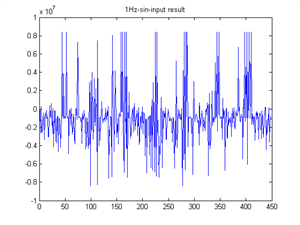
    However, my outputs are not good. They are not completely random stuff: using 1Hz  sinusoidal input, there is obviously some peroidical pattern in the result, and using zero-input, the output is basically zero, but looks very, very noisy. Some sample outputs are attached, could you help me finding out the problem (wiring or coding)?

  • Hi Xing,

    I'm glad to hear you're making progress!

    You have two things you need to check:

    1. First go back and look at the SPI communication on the oscilloscope! Does the communication look correct and are you seeing good data on the scope?

    2. Next, take a look at your code. Is you code capturing the same data you see on the oscilloscope? You could be running into issues with the math operations. Take a look at this related topic:

    Best Regards,
    Chris

  • Now the transmission between the ADS1258 and Arduino works fine. For example, when the clock and output look like this:

    On the oscilloscope, it reads:

    10001101
    10111111
    01100000
    11111100

    The code reads the signal as:

    141
    191
    96
    252

    Which indicates the data reading is accurate.

    However, after I applied a sinusoidal signal, it still generate random stuff like this:

    201
    128
    0
    0

    146
    36
    192
    44

    143
    10
    254
    100

    149
    0
    159
    30

    141
    28
    174
    162

    The data is in the form of:

    Status byte
    Data byte 1
    Data byte 2
    Data byte 3

    Combining 3 data bytes together in each data transmission point using 2's complement format, and then putting all data transmission points together, it just won't form a sinusoidal wave.

    Now I wonder that the ADC converter is not configured right to collect data from DIFF0 channel. I did not change anything in the register, and that may be the reason that it did not work. Now the register settings are:

    0Ah
    83h
    00h
    00h
    FFh
    FFh
    00h
    FFh
    00h
    8Bh

    Should I change it into:

    0Ah
    83h
    00h
    01h
    00h
    00h
    00h
    FFh
    00h
    8Bh

    To enable only DIFF0? By the way, if I enable both DIFF0 and DIFF1, how should I read them in the same time?

    Except how to configure the ADC converter, the other question is how to interpret the digital output. For example, when the output is:

    141
    28
    174
    162

    10001101
    00011100
    10101110
    10100010

    What is the physical meaning of the data? Does it mean in continuous transmission, the reading of channel 14 (01101, AIN4) is 1879714 (3 data bytes combined using 2's complement format)? But I did not attach anything to AIN4, how did it get such a large reading?

  • Hi Xing,

    Regarding your results...

    Xing Wang said:

    Now the register settings are:

    0Ah
    83h
    00h
    00h
    FFh
    FFh
    00h
    FFh
    00h
    8Bh

    You are using the default register settings. By default, the ADS1258 is in auto-scan mode and it is cycling through all of the single-ended input channels.

    If you want to set the ADS1258 to read from a single channel, then you'll need to set the MUXMOD bit to 1 and then configure the MUXSCH register to the appropriate channel.

    Xing Wang said:
    To enable only DIFF0? By the way, if I enable both DIFF0 and DIFF1, how should I read them in the same time?

    Set MUXMOD = 1 (in the CONFIG0 register), then for ADCINP = CH0 and ADCINN = CH1, set MUXSCH = 0x01.

    When you read data, you'll be reading the differential voltage applied between AIN0 and AIN1 (so long as you do not violate the "Absolute Input Voltage" specification on page 3 of the ADS1258 data sheet).

    Xing Wang said:

    However, after I applied a sinusoidal signal, it still generate random stuff like this:

    201
    128
    0
    0

    146
    36
    192
    44

    143
    10
    254
    100

    149
    0
    159
    30

    141
    28
    174
    162

    If you go look at the meaning of each status byte it will show you that the ADS1258 is capturing data from AIN1, AIN10, AIN7, AIN13, and AIN5, respectively. This can partially be explained by that fact that the ADS1258 is operating in auto-scan mode; however, why are the channels out of order? Either this data is not being read correctly OR you are losing data (not reading it).

    Xing Wang said:
    What is the physical meaning of the data? Does it mean in continuous transmission, the reading of channel 14 (01101, AIN4) is 1879714 (3 data bytes combined using 2's complement format)? But I did not attach anything to AIN4, how did it get such a large reading?

    A status byte of "141" or "0x8D" means that this is new data on channel AIN5 (channel AIN5 is the differential voltage between AIN5 and AINCOM).

    The data "28", "174", and "162" can be combined into a single number "0x1CAEA2" or "1879714" (decimal). You would then multiply "1879714" by the LSB size to get the voltage result.

    What is your reference voltage?


    Best Regards,
    Chris

  • Finally I got some voltage data:

    Changes made:

    Write the configuration register as {0x0A,0x83,0x00,0x01,0x00,0x00,0x00,0xFF,0x00,0x8B} (auto scan mode with only the channel DIFF0 enabled)

    Change reference voltage switch settings, S1 from middle to left, S2  from middle to left to use AVDD and AVSS as reference voltages.

    Now I still have two problems:

    First, my sampling rate is very low. On the plot, there are only 144 data points, which indicates the sampling rate is about 35 SPS (the signal is 2 Hz). However, with only one differential channel enabled, the desired sampling rate should be several kSPS. Is this due to the slower clock rate of Arduino (4 MHz) compared to that of ADS1258 (16 MHz, but this is unlikely because the sampling rate is low by a factor of hundreds instead of 4)? Or is it because the serial monitor cannot display data fast enough? Or is there other possible issue? When I enable two differential channels DIFF0 and DIFF1 (configuration register={0x0A,0x83,0x00,0x03,0x00,0x00,0x00,0xFF,0x00,0x8B}), the data from the two channels are out of order. What may cause the loss of data?

    Second, there are "bad" data points in my reading. With only DIFF0 enabled (configuration register={0x0A,0x83,0x00,0x01,0x00,0x00,0x00,0xFF,0x00,0x8B}), my status byte reading is not always 0x80, which corresponding to DIFF0 channel. There are incorrect status byte readings like 0x81,0x82,0x84,0x90,0x98,0xC0, although most of the status byte readings are 0x80. Why does this happen?

    Thank you for helping me out!

  • Hi Xing,

    To answer your questions:

    Xing Wang said:
    First, my sampling rate is very low. On the plot, there are only 144 data points, which indicates the sampling rate is about 35 SPS (the signal is 2 Hz). However, with only one differential channel enabled, the desired sampling rate should be several kSPS. Is this due to the slower clock rate of Arduino (4 MHz) compared to that of ADS1258 (16 MHz, but this is unlikely because the sampling rate is low by a factor of hundreds instead of 4)? Or is it because the serial monitor cannot display data fast enough? Or is there other possible issue? When I enable two differential channels DIFF0 and DIFF1 (configuration register={0x0A,0x83,0x00,0x03,0x00,0x00,0x00,0xFF,0x00,0x8B}), the data from the two channels are out of order. What may cause the loss of data?

    Are you using the X1 crystal on the EVM to generate the ADS1258's master clock, or are you applying an external clock to the CLKIN pin?
    If you're using the crystal, the ADS1258's internal clock will run at 16MHz; however, applying an external clock will scale the ADC data rate accordingly.

    You may not be capturing all of the data on the SPI bus, especially if the status bytes shows the channels out of order in auto-scan mode!

    Can you probe /DRDY on a scope and measure /DRDY's period? That will tell you the ADC's data rate.

    Xing Wang said:
    Second, there are "bad" data points in my reading. With only DIFF0 enabled (configuration register={0x0A,0x83,0x00,0x01,0x00,0x00,0x00,0xFF,0x00,0x8B}), my status byte reading is not always 0x80, which corresponding to DIFF0 channel. There are incorrect status byte readings like 0x81,0x82,0x84,0x90,0x98,0xC0, although most of the status byte readings are 0x80. Why does this happen?

    If you're losing data, you may be incorrectly reading from the SPI interface!

    Your SCLK is 2MHz, correct? (I think that is what I observed on one of your oscilloscope screenshots, and that should be plenty fast to capture all of the data).

    Are you polling /DRDY or are you using /DRDY as an interrupt? Polling can often miss data.

    Also, the SPI communication looked noisy with overshooting on each of the SPI signals. This could be an artifact of the oscilloscope or it may be a signal integrity issue resulting from inductive jumper wire connections to the EVM. Try to keep these wires short and close together. Wrap a ground wire around all of your other wires or shield them to clean up the SPI communication!

    Best Regards,
    Chris

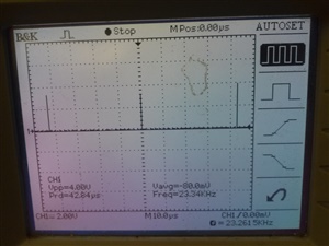
  • I did not connect any signal on CLKIN pin, so I assume that it uses build-in clock. My DRDY pulse signal is attached:

    The frequency is correct (about 23 kHz), but when I look at my SCLK signal, it still only has about 50 Hz (count 4 bytes 32 clock as one pulse).

    In my code, my algorithm looks like:

    if (digitalRead(DRDY)==LOW)

    {

    read 4 data bytes

    }

    So the DRDY signal is used as an interrupt, but it still loses data...

  • Hi Xing,

    The ADS1258 is converting and you're getting the correct data rate. I think your code isn't working as you'd expect it to...

    Xing Wang said:

    In my code, my algorithm looks like:

    if (digitalRead(DRDY)==LOW)

    {

    read 4 data bytes

    }

    So the DRDY signal is used as an interrupt, but it still loses data...

    This seems like it would work like an interrupt; however, it is not the same an interrupt. A true interrupt would continuously monitor the /DRDY signal (for the most part), but the IF statement only monitors /DRDY when your Arduino is executing this instruction!

    Perhaps the Arduino is not returning to this instruction (the IF statement) fast enough! If so, it would explain the loss of data.

    Best Regards,
    Chris

  • Sorry for the late reply, I was not work on the ADC converter/microcontrollers last week...

    So I am almost sure that the data is generated from the ADS1258 with correct data rate, but the Arduino reads it too slow: first, my impulse frequency of DRDY is correct (23 kHz), but I cannot see that it stays high for a data reading time on my oscilloscope. Second, if I measure SCLK channel and consider a data reading time(contains 32 clocks) as one pulse, the frequency is less than 50 Hz. Third, the NEW bit in the status byte is always 1, indicating that the data is not sent to the Arduino fast enough.

    So you mentioned my code does not work as an interrupt, but how? How should I program the Arduino to make it continuously monitor the DRDY channel/return the IF statement reading fast enough?