This thread has been locked.

If you have a related question, please click the "Ask a related question" button in the top right corner. The newly created question will be automatically linked to this question.

ADS1248

Other Parts Discussed in Thread: ADS1248

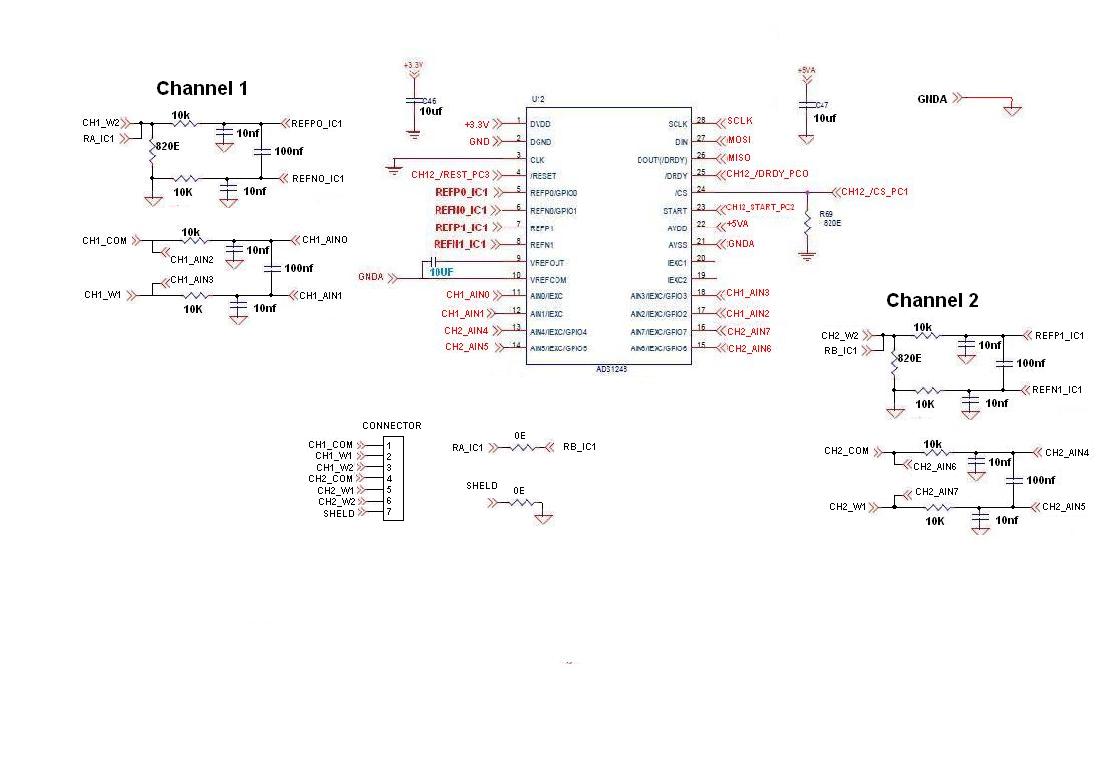
Thank you very much for your timely response. Sorry that i had uploaded a old schematic before. The present circuit schematic has been uploaded now in which i hav been facing the fluctuation issues . And the VREFCOM has been connected to AGND in this schematic as suggested but problem still persists .

The problem is that if the ic is sampled at 20 sps a stable reading is obtained in the output, But when the sampling is done at 80 sps , there is a huge fluctuation in the output count obtained from the Ic.

The reason for going for a higher sps is the conversion time. Sampling @20sps with 6 ADS1248 IC's for reading 12channels takes a time of ~3sec for convertion. So for bringing down the conversion time, we are planning to sample @ 80 sps which may decrease the conversion time to ~1.2 seconds. sampling @80sps is also reading the proper value , but the fluctuation has been the issue.

Any help will be appreciated. Thank you in advance. .

  • This is schematic of the same . 

  • Surender,


    I think that your problem may be that your circuit is susceptible to line cycle noise.

    If you go to pages 26 and 27 of the datasheet, you can find information about the frequency response of the digital filter of the ADS1248. At 20 SPS for a data rate, a 50Hz signal is attenuated by about 70dB or more. At 80 SPS, you have a different frequency response and a 50 Hz signal is probably attenuated less than 20dB.

    The line cycle noise may be coming from your power supply or it can be coming from your circuit getting some EMI. There are ways that you can test this. I'd try powering this off of batteries which should not have any line cycle noise. I'd also try to build a conductive enclosure that can keep out radiated emissions from anything in the area (lights, motors, etc.).

    If you don't think that's the problem, see if you can collect a large sequence of data, record the ADC output, and post it back here. If the 50Hz noise is the problem post back to let me know that you found the source of the noise.


    Joseph Wu
  • Surender,


    One of my colleagues pointed out that on the schematic, you still need to connect VREFCOM to AGND. There's a description in the datasheet on page 29. VREFCOM needs to be connected to an AC ground through a resistance of less than 10 Ohms.

    Also, is AGND connected to GND?


    Joseph Wu
  • As asked, i have recorded and Attached the data of ADC output of both 80-SPS and 20-SPS. Their is no possibility of radiation emission, as the ADS1248 IC's are placed in a conductive enclosure.

  • Surender,


    Can you send this to an excel spreadsheet? It's hard to see the data this way.


    Joseph Wu
  • Surender,

    I managed to copy all of the data from your picture to a spreadsheet (next time it would be easier to send me an excel file). The 80SPS data looks a bit worse than the 20SPS data however, it's not all bad.

    Looking at the statistics of the data, the average and standard deviation of the 80SPS data is 1662723 and 42 codes respectively. For the 20SPS data, this goes to 1663072 and 30 codes. In the average, there's a difference of about 350 codes in the average and 12 codes in the standard deviation. The offset seems a bit large, but the noise difference seems like it could all be explained by a drift in the measurement. Look at the plot in the attached spreadsheet.

    I'll also note that I took off the first point in each of the measurements. In the 80SPS case, the first data point was almost 200 codes below the average measurement. In the 20SPS case, it's not as low, but it is the lowest value in the sample set.

    Looking at a time plot of the data, it looks like the 80SPS has more settling to do before it reaches final value. I'm not sure about how the data is taken and the differences in setting up the measurement.

    Is there some settling in the way you set up the data? Are there large resistances and capacitances on the input pins used for filtering? It's possible that there is some difference in the measurement because of the differences in input current from 20SPS and 80SPS.

    Joseph Wu

  • Attaching the spreadsheet....ADS1248_20SPS_80SPS.xlsx

  • No, their is no settling in the way the data is setup. The capacitors and the resistors are connected in the input as shown below. The circuit is same the for both 20 and 80 sps.

  • Sorry for the inconvenience, next time i'll make sure the data is clearly readable for you. Thanks a lot for your precious time.

  • Surender,


    For all of the input filters (this would be for AIN0, AIN1, AIN4, AIN5 as well as for the references REF0 and REF1), I would remove all 10k resistors and replace them all with 1k resistors. That would be all 8 resistors in total. If you use the other input channels, you will likely need to replace them as well, but start with these 8.

    I suspect that the the input current reacts with this resistance to cause a voltage offset. In the ADS1248, the input current increases from 20SPS to 80SPS data rates and I suspect this change is adds to both the noise and offset. This input current comes from the chopping of the PGA and likely has some variability depending on the temperature and voltage and other factors.

    As an experiment, replace these resistors and check the result to see if it's better. Regardless, I think that 10k is a bit too high.


    Joseph Wu
  • By changing the value of the resistor from 10k to 1k the fluctuation has been reduced to some extinct but the read value is still not stable. The collected data after the changing the resistor from 10k to 1k has been attached in the excel format. And the converted real time data has been attached in the word format. 

    samples_2.xlsx

    8461.converted data reading.docx

  • Surender,


    It looks like we're moving in the right direction for the noise performance. Checking the noise performance, the 80SPS noise is now as low as the 20SPS noise you had been measuring earlier.

    I've looked at the converted data file (written in word), and I don't understand what I'm looking at. Can you explain what the two columns are and what they represent? I'm not sure if you are switching in and out of 20SPS and 80SPS modes. For the 80SPS are you getting an intermittent low reading? Or are you just making two 80SPS readings and then switching back to 20SPS. I'll need a lot more explanation to understand this. Try to remember that I don't know much about your system.

    Here are a few more things that I'd thought about. The next thing I'd like to try is to remove the resistors going into REF0 and REF1 and replace them with 0OHm resistors. The input current for the reference pins can be an order of magnitude higher than the input current for the analog inputs. I'd like to try to eliminate that effect. I'd say that we can leave the analog input filter resistors at 1kOhms for the time being.

    Let's increase the capacitance for the input filtering, changing the 100nF cap to 1uF. This will lower the bandwidth back to what you had before.

    I'd asked about this earlier, but what are you using for your power? Is this battery powered or something that is plugged into an outlet? If it's plugged into an outlet then there may still be 50Hz noise inside the enclosure. If the power comes from USB, then there may be other noise coming from the computer.

    Also, for your data next time take a set of 1024 points for each. It might help to get an FFT run to see if there is any frequency content in this measurement.


    Joseph Wu
  • Actually, we are using ADS1248 for calculating temperature value (ADC count is converted into temperature by using some formula). The converted data file in word was representing temperature reading of 1st ADS1248 IC with 2 channels. I am using 2 separate Program. One Program with 80SPS, flashing the program and recording the data(reading) of samples (ADC Count) and corresponding temperature value, later after storing the data of 80SPS, i am flashing another program with 20SPS to the same board and recording the data(reading) of samples (ADC Count) and corresponding temperature value.

    Present schematic as asked, replaced the 1k resistor to 0E @ REF and replaced 100nf to 1uf. i don't see much fluctuation now. but, still their is a dip (Change) in temperature data @ 80SPS. i have attached an word file's, one with 80SPS samples and change in temperature value of single channel. Another word file with 20SPS, were their is no much change in temperature value of single channel.

    in that attached word file you can see a connector connected to a resistor (the resistors are connected to 10meter length wire to the connector) and some explanation how i am using the resistor to find the Temperature value.

    we have used 158.08ohm resistor at channel 1 for 152°C and 118.08ohm at channel 2 for 46.6°C. (attached temperature_resistor chat)

    Temp_resistance chart.pdf

    20sps.docx

    80sps.docx

    The power supply we have used is a socket plugged 230 volts to 110 volts external dc converter which drives the 110 v to 24v regulator and the 5v is extracted from the 24v regulator by using another 24 to 5 volts regulator. The reason for using so many regulators is that different section in the board require different voltages hence all those many regulators. And all regulators are hand picked which has good signal-noise performance.

    REF = 0E.xlsx

    samples are placed in xl sheet. This samples are taken after the changes made in the circuit i.e. REF to 0ohm. and capacitor to 1uf.

  • Surender,


    I'm sorry I didn't respond back to the post, I was out of town on Friday through the weekend.

    I've looked over your posts and I'll need some more time to consider it. I would like to point out a few things and get a few responses.

    First, I'd like make sure how you have the measurement set up. It looks like a ratiometric measurement with RTDs. Are you routing matched excitation currents through the positive and negative inputs? What voltage do you have on your reference? What voltage are you measuring on your inputs? What current are you using? Have you tried removing all of the series resistance entirely?

    I would also say that even if you are using low noise regulators, you still are likely to have some sort of 50Hz noise in your system. There could be some radiated emissions or ground loop currents that can spread 50Hz noise. Also, with such long connections to the sensor, you can pick up radiated emissions from the something external to the device. Even though you have an enclosure for your board, I think you're still going to be subject to noise.

    Again, I'll continue to read through your comments here and get back to you.


    Joseph Wu
  • Surender,

    Now that I've looked at some of what you've posted, I have a few comments and recommendations.

    First, let's start with the data in the docx files. I've looked at the data that you sent in the docs, which look like the same data in the excel file. Is that correct?

    I can't find a correlation between the two columns and they do not line up, I'm still not sure what that is.

    Looking at the excel file, if you look at the entire plot, it doesn't look too bad. There is a small amount of drift for the 80SPS data, and less for 20SPS:

    However, if you look at the data closely, you can see that there is some pattern to the noise. It's not random. It looks like it alternates between different values. Instead of looking at the entire stretch of data, look at the first 30 points:

    It seems that there is still some sort of periodic noise in the system that shows up in the measurement.

    Now, let's go to your setup. Now that I can see the RTD measurement, let me assign some numbers to the values. I'm going to guess that you are using both excitation current sources so that they drive the RTD (or resistor) and collect the current in the reference resistor which is 820 Ohms. Are you using 1.5mA for both current sources? This would give about 2.46V for the reference input. I'm also going to guess that you drive one current source to AIN0 and the other into AIN1 to try to match the parasitic resistance for a 3 wire measurement.

    For the 158.08Ohm measurement, that would give you about 0.237V. You might be using some gain. Based on your data, it looks like PGA=2.

    If this is what you are doing, then you need to remove the 1k filter resistors. In this case, the current mismatch (and parasitics) multiplied by the resistor mismatch is an added error in the measurement. By changing the data rate, you also change the input current and that multiplied by the 1k resistors gives more of an error. I'd try removing this. I didn't realize that you were doing a ratiometric measurement that had added current through the measurement leads. Try removing this and see if it eliminates the temperature value dip that you see.

    Additionally, it still looks like you need to clean up noise in your system (as shown in the 30 sample read from the 80 SPS and 20 SPS data. Some of it may be your grounding in your board and some of it might be pickup from long lengths of wire in your setup.

    Joseph Wu

  • Joseph,

    It is OK Mr Joseph, even i was held up with a pile of work . Actually we are not using the ratiometric measurement with RTD's . We are using the routing matched excitation currents through positive and negative inputs. Will post voltage reference and the remaining detail on Monday as i travelling out of the city on a different project. As asked i'll replace 1k series resistor with 0ohm resistor and post the result by Monday.
  • Joseph Wu,

    Yes, its the same ADC data in Excel file which was Place in World file. I have changed the Series resistor from 1K to 0ohm, At bottom i have placed the ADC count and Temperature value in a Single Excel file with correct alignment (readings have Been recorded after the change of  Series resistor).  The 24bit ADC count value is calculated as temperature value.

    We are using 1mA for both current sources. This would give about 1.64V for the reference input. we drive one current source to AIN0 and the other into AIN1 to try to match the parasitic resistance for a 3 wire measurement.

    For the 158.08Ohm measurement, that would give about 0.41V. Gain used is 2 (PGA=2).

    this is the Present circuit as asked. 

    0ohm 80sps.xlsx

    Even after changing the 0ohm their is a dip in temperature value at 80SPS (the changed temperature value is colored Red in Excel sheet ).  i have also recorded the reading of 160SPS, were i can't find any dip temperature value, but fluctuation is more. 20SPS is working good without many fluctuation.

    And regarding the noise level we are still working on it.

  • Surender,

    I believe that you have a communication error in the 80SPS mode. This looks as if you have started reading out a conversion and have been interrupted by a new DRDY indication.

    I wrote a blog about communication errors a few months ago and I'll put a link below. This looks like the one addressed in Figure 3, where you start reading the data, are interrupted by a DRDY indication and then continue reading.

    e2e.ti.com/.../help-i-can-t-talk-to-my-data-converter-what-s-wrong

    In your excel file, column C and column D still don't match up, but at least I can see the data error. It looks like the data is reading one full byte and then starting on a new piece of data. As an example, row 715 reads 1579180, which translates to hex as 1818AC. It looks as if the first 18 is the start of a read, then it starts over to get 18AC (which also happens to be the start of the next data in row 716). In the attached picture, this happens four more times in short succession.

    This could be an error where you wait too long to get the data after a /DRDY indication. Do you use an interrupt to get the data out after a /DRDY? Is it possible that this could be a problem with the micro mixing up or losing bytes during the reads?

    One thing that is possible to try is to set the device in SDATAC mode to stop updating the DOUT register every time there is a new data available. Then you would use the RDATA to get the data when it is ready without the possibility of interruption when a new data comes up. SDATAC does not stop conversion, it only stops the data update on the DOUT register.

    Check this out and see if it helps. Let me know if this shift resolves itself with the SDATAC mode and subsequent RDATA reads.

    Joseph Wu

  • Joseph Wu,

    As asked i had changed the SDATAC and RDATA value in my program. but no improvement,  the shifting still occurs and the temperature value changes.80SPS_13_sdata.txt

    in the above notepad, 1st row is time, 2nd row is Address, 3rd row is Temperature value of cahnnel-1, 4th row is Temperature value of cahnnel-2.

  • Surender,


    Again, based on what I've seen, including the latest data, this is not a problem with the ADC. This is a problem with getting data out of the ADC.

    From the raw data, the error looks like you are extracting the first of three bytes, then instead of getting the next two bytes, the read starts over and then gets the first two bytes of the next conversion.

    This is either from the timing of the /DRDY pulse, or you are losing bytes for other reasons.

    What are you using for the microcontroller? Does this come into a computer through a USB interface? It's likely something in those steps that is giving you this error.

    To solve this, I think you're going to need to get a logic analyzer and try to find this problem, starting with the DOUT line and then trace steps back through the microcontoller, the USB interface, and back to the computer. Again, based on the raw data, it looks like this is not a problem with the ADC but with your data extraction.


    Joseph Wu
  • We are using a STM32F103 ARM controller to which the ads1248  ic is connected and the data is being read from the ARM controller via a RS485 interface to the PC .

    i have attached my code below for single channel.

    3782.temp code for channel1.docx

    i have defined line in blue color.

  • Surendar,


    I know more about the ADC side of things than the processor side, so I'm going to be of less help on solving this type of problem.

    That being said, I can still offer a few suggestions.

    1. I don't see that you issue an SDATAC command anywhere. You will only need to send this command once. This is necessary for you to stop updating you DOUT register every time a new data is available. Also, this ensures that the RDATA gets the most recent data.

    2. I see that you're polling the DRDY to wait to read the device. If you don't use the SDATAC to stop the DOUT updates, an interrupt can be used to force the read of data. I'm not sure how long the polling interval is, or if it is consistent. If you take too long in reading back the device then a new data will interrupt the last read.

    3. I think you need to look at the output of data with a logic analyzer. You'll be able to see any timing issues or errors and see how data is coming up. You can also see how long it takes to read data, and if there are any reads that take an unusual amount of time.

    Again, I'm not expert in coding, so it's a bit hard for me to look through this and see where the problems are coming from.


    Joseph Wu