This thread has been locked.

If you have a related question, please click the "Ask a related question" button in the top right corner. The newly created question will be automatically linked to this question.

ADS1248: ADS1248 single ended measurement

Part Number: ADS1248
Other Parts Discussed in Thread: ADS1220, REF3030, ADS124S08

Hello,

i have to use the ADS1248 in one Project. A differential measurement is not really needed. I only have to measure a voltage over a Resistor with fixed (1mA) current.

Therefore i have connected one Pin of the resistor (which has to be measured) to GND, the other one to a (positive) Input channel.

What to do with the negative Channel? Can i connect it simply (or through a resistor) to GND to have a single ended measurement with full ADC Range?

From Datasheet i see some "pseudo-differential" measurement, where the negative Channel is not connected to GND, but to VCC/2 or something else. What is the Advantage here?

Regards

Daniel

  • Daniel,


    The problem is that you can't connect the negative input pin to ground because of the input range of the PGA at the front end. At a gain of 1, the input is limited to GND+0.1V. At higher PGA gains, the input is limited even further because the gain limits the input common mode range. There is an explanation about the PGA starting at page 26 of the ADS1248 datasheet.

    In order to measure the current, I would advise sinking the current through the resistor into something other than ground. It is possible to sink the 1mA into VREFOUT of the ADS1248 internal reference. Connect VREFCOM to AVSS/GND on when using a unipolar supply. This will sink the 1mA into a voltage of 2.048V above GND.

    To make the measurement, your negative input would be at bottom of the resistor, connected to VREFOUT and the positive input would be at the top of the resistor, sinking the 1mA.

    If you still need an input that goes all the way to GND, I would consider using the ADS1220 or the ADS124S0x devices. Both are similar to the ADS1248 but the user can bypass the PGA so that the measurement input can go all the way down to GND-0.1V or GND-0.05V respectively.


    Joseph Wu
  • Dear Joseph,

    thank you for your Explanation.

    Instead of sinking the current into VREFOUT would it also be an Option to connect an external Reference of 2V to the negative Channel instead? At the same time i would like to sink the current through the resistor into GND as it currently is.

    I am thinking about this soution because this would be not such a big Layout Change for the Hardware we currently have.

    Regards

    Daniel

  • Daniel,


    I'm not sure that connecting the negative input to an external 2V reference would help you very much. It depends on the nature of your measurement. I wouldn't be a problem to make the connection, because the it is within the range of the operation for the negative input.

    However, you need to ensure that the current is there and you need enough resistance to keep that voltage 100mV above AVSS. If there is no current or the resistance is too low, then the voltage drops below 100mV and would be outside the range of the PGA. Additionally, you would be subject to error in the reference, so you might not be able to make an accurate measurement without some sort of calibration.

    Do you have a schematic you could share? There might be other alternatives to using an external reference.


    Joseph Wu

  • Dear Joseph,

    here is a screenshot of our design.

    As you see we have connected AIN5-7 (negative channel) through a voltage devider to a precision voltage reference of 3V, so that we have 1.5 Volt Level on These Input channels. On AIN0 we have connected a Precision 1k Resistor for a calibration measurement, on AIN1 we have a connector X160 where we connect a PT1000 Temperature sensor. IEXC1 is configured to have the 1mA Current Source enabled.

    Concept is now to Switch on T12 first to have the 1mA flow through R162 and make one calibration measurement. Second step is to Switch off T12 and Switch on T13 and let the 1mA current flow through the connected PT1000 into GND and measure again. Perhaps the voltage devider R149/R161 Needs to be adjusted to match the Voltage we have on the positive channel while measureing the Refernece Resistor R162.

    Is this a possible setup?

  • Daniel,


    Basically you could do this type of a measurement but there are some issues to keep in mind. There is some error from the REF3030 which would offset the 1.5V that you're setting up with the voltage divider.

    Also, I would recommend removing R156 and R157. During the calibration, T12 is sourcing 1mA into 2.5kΩ which means that the stack voltage is 2.5V. With AVDD = 3.3V, you have a compliance voltage to the positive supply of 800mV. This is a bit small, and you'll see that the IDAC current will be much less than 1mA. Look at Figure 41 from the datasheet for IDAC voltage compliance. While this figure is for a 5V supply, you'll see that at 800mV of IDAC voltage compliance, with a 1mA IDAC, you're probably going to be near 850uV. If you remove R156 and R157, you won't have this problem. If you need to have them, then make them 500Ω.

    If the PT1000 is connected to the terminals of 1 and 2 of X160, and the PT1000 is actively measuring a hot temperature, then you may need to make further adjustments. At very hot temperatures the PT1000 will get to 3kΩ or 4kΩ of resistance. That would also increase the stack voltage so that the IDAC output would drop because of the compliance voltage.

    However, I'm still not clear on what you are trying to measure. Are you just trying to measure a two-wire PT1000? If that's the case, I would just used a ratiometric measurement with a 4kΩ precision resistor as a reference from REFP1 and REFN1. I also don't see why you're using T12 and T13 when you could just send the currents to IEXC1 and IEXC2. I can think of a few different ways to make this measurement, but I'd just like more of a clarification of what exactly you want to measure.


    Joseph Wu
  • Dear Joseph,

    indeed i am trying to measure a two wire PT1000. We have temperature of -100 to 100°C maximum. The measurement must be at least as precise as 0.1°C, if possible better.

    The reason for the Transistor ist, that we do not only have the one channel like shown in the schematics above, but we have up to 6 channels we have to measure one after each other. Every channel has one transistor to switch the current to the channels.

    Thank you for pointing me to the issue of voltage. i will adjust R156 and R157 to 500Ohms. 

    Regarding the offset of REF3030: I am aware of this, also the Voltage Divider R149/R161 brings more error due to tolerances of these resistors. That's why i want to make the calibration measurement with R162. Don't you think that i can calibrate the offset error with this calibrtion measurement?

  • Daniel,

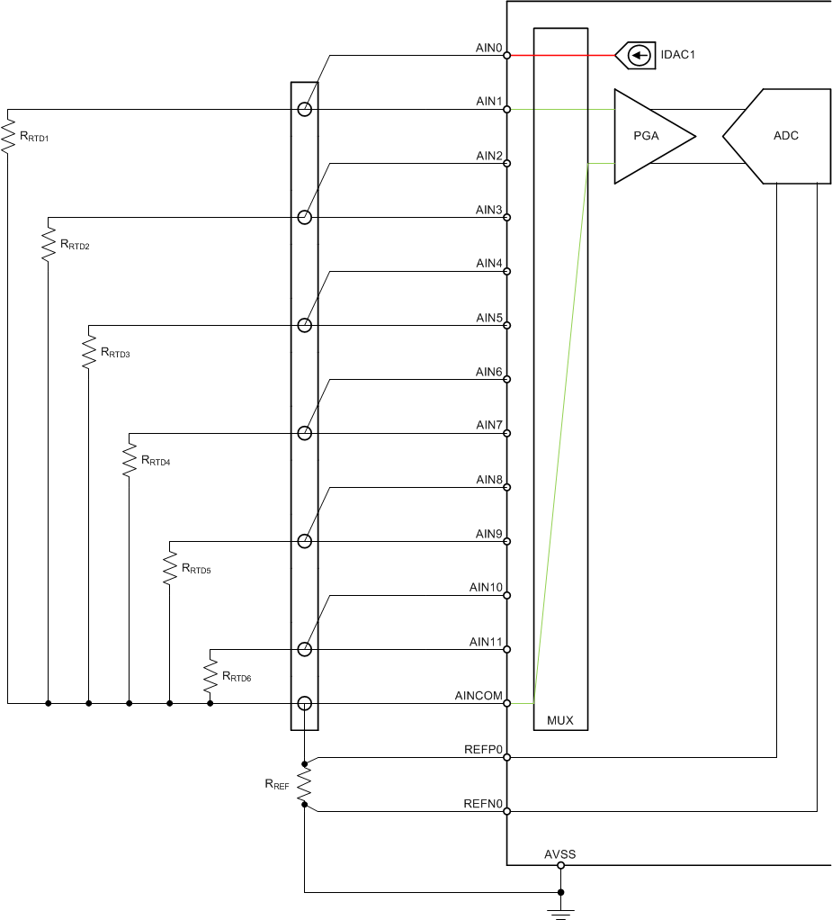
    I think it would be better to have a slightly different setup and simplify the measurement. Also, I'm going to suggest that you use the ADS124S08, which has a few more analog inputs. Here is an example of how you would measure 6 two-wire RTDs that should be more accurate. I've drawn this without any input filtering. In industrial environments, you'd use simple RC filtering to reduce any EMI/RFI to reduce the noise. If you don't need the filtering, you may reduce the analog inputs that you use, and drive the RTDs directly through the analog input used to measure the input.

    The IDAC excites the RTDs individually. The diagram show a measurement for RTD1. IDAC1 goes to AIN0 and excites RTD1 and the reference resistor. ADC measures the RTD using AIN1 and AINCOM. To measure RTD2, IDAC1 gets routed to AIN2 and the ADC measures from AIN3 to AINCOM, and so on.

    Because the same IDAC current drives both the RTD and the reference resistor, this is a ratiometric measurement. To get the RTD value, you don't need to calculate the voltage and the ADC output is a ratio between the RTD resistance and the reference resistance.

    ADC output = 2^23 * PGA gain * (RRTD / RREF)

    The reference should be larger than the RTD resistance. The reference represents the positive full scale range. You will need a precision resistor for RREF. It should be high precision and low drift. Any error in RREF will appear as a gain error.

    In the design, you need to make sure that the RTD sensor voltage is within the input range of the PGA. Also, confirm the voltage across RRTD + RREF is within the compliance voltage of the IDAC (if the voltage is too high, then the IDAC current starts to drop off).

    The ADS124S08 datasheet has an example application at the end of the datasheet. It is for a three wire RTD measurement, but it does outline a design procedure. Regardless, I would certainly consider the ADS124S08 for your design.

    Joseph Wu

  • Dear Joseph,

    thank you for the good explanations. A few questions:
    - This design requires a Powersupply with 4.5V or greater due to Voltages across RRTD + RREF, which is at least above 2V when making RREF greater than RRTD and measuring temperatures above 0°C due to the IDAC compliance Voltage requirements. Bad thing, is that i have only 3.3V available on my PCB and want to avoid a 5V Supply, if possible. Do you see a chance to handle this?
    - On another PCB i am in a similar situation, but need to measure only 4 RTD. Can i use ADS1248 in the same way, but use IEXC1/2 as one additional needed current source?
    - For the concept you described, is there an additional external voltage Reference needed?
    - when we use filtering like described, which precision do you expect for the RTD measurement?

    Unfortunately my customer is pushing a bit to get my previously proposed solution running. He has put much effort in development of filtering and external current source curcuit with OPAMPS in an old project and wants to reuse this. Idea was to just avoid the external current source and use IDAC of ADS1248 instead. Do you think that my proposal would be possible with the modifications you described earlier (remove 1k5 Rsistor and put AVDD/2 to one channel as negative input). I AM aware of pro's and Con's now and want to discusse these with the customer next week. So do you think that the measurement is generally possible this way?

  • Daniel,


    If you are making measurements from -100°C to +100°C, your resistance range will be from about 600Ω to 1400Ω for the PT1000. If you use a reference resistor of 2800Ω, then the total resistance will be 4200Ω and if you use a 500uA IDAC current (with a PGA gain of 2) then the total voltage is 2.1V, with a reference voltage of 1.4V. This would be within the input range of the PGA and within the IDAC compliance voltage. I don't think you need the 5V supply at all.

    If you only need 4 channels, I think the ADS1248 would work. You would need to use the IEXC pins to source current, but you have enough to make the measurements. I would note that the ADS124S08 does have better specifications for gain error and offset (and a better specification for voltage compliance).

    As I've described it you don't need an external reference. You do need to enable the internal current source because it is used to generate the IDAC current values, but there's no need for an external reference.

    I'm not sure what precision to expect. There is a certain amount of error associated with the RTD itself. In many cases the RTD has a 0.1°C error. You should be able to calculate an approximate error based on the gain error, offset and noise seen in this measurement. I will say that my method should work better than what you had previously drawn. In your setup, you'll need two measurements to compare and calibrate out the error (both absolute error and any drift) in the reference resistor and the additional reference. Additionally, the REF3030 will add noise to the measurement. I see this as a complicated

    In the solution I describe, it's simpler, requires only a single measurement, and I only need to worry about the reference resistor accuracy and ADC gain error.


    Joseph Wu
  • Dear Joseph,

    we built up the setup and the temperature measurement seems to work fine.
    But when we tested it at the EMC Lab with interference injections,
    the measurement results were corrupted. So more filtering is required.
    Until now, we used the PI-Filter NFL21SP206X1C7D on every channel of the ADC.
    We are not filtering the signal on the reference resistor at the moment. This would be our first step.

    Can you recommend a suitable solution for this problem?

    Regards
    Friedrich
  • Friedrich,


    Generally, EMI is a system level problem and dependent on many factors associated with physical layout of the board and system. I don't know have any recommendations on specific input filters. You may be able to remove the effect with some aggressive RC filtering, but it would require some experimentation. Increasing the capacitance will give a lower impedance path to dissipate differential EMI signals, or shunt common-mode EMI signals to ground at high frequency

    Normally, you need to consider the EMI while doing the layout of the board. Start by reducing long lead wires in the signal path. This would include connections in your testing system if they are going to some controller. If you are measuring RTDs, then you might have a long lead attached to the input of the system that may need to be shortened.

    Also, reduce any large electrical loops in that might be created in your circuit. This certainly includes the input and reference signal paths, but may include the power and digital lines as well.

    Shielding certainly helps with EMI. In layout, using the power and ground planes over sensitive signal paths will certainly reduce the effect of EMI. On top of the board, it may be worthwhile running tests with partial shielding to see where the EMI causes the most problem.

    Out of curiosity, how does the EMI cause a problem? However were the measurements corrupted? Does the device have a shift in gain error or offset? Is there a reset of the device? When EMI is removed, does the system return to normal?


    Joseph Wu
  • Dear Joseph,
    in the layout we already implemented these hints.
    When the measured temperature is 20°C in normal state, the value is randomly bouncing in a range of +80°C to -40°C when the influence is running.
    The measured values are correct again, immediately when the influence is stopped.
    So the device works fine all the time.
    We are not able to determine, whether we have a shift in gain error or offset while influencing,
    because its not possible to do some measurements in the circuit while the influence is running.

    The problem we see is that we have cables of 2m between the PCB and the PT1000, so we have great antennas to recieve noise.
    These cables are given by our customer and they are not shielded.

    Do you have experience in EMI filtering for such applications?
    Do you know a approved filter that we can use in a first try and where we can start adjusting?
  • Friedrich,


    I don't have any specific EMI filter device recommendations. I just don't have much information to provide on the topic.

    Previously however, I did collect a few presentations about EMI in one post for the ADS1248. You can find the post here with links embedded in the text:

    e2e.ti.com/.../1396994

    One last thing I'd like to add is that you should also add filtering to the reference input. The reference is an input just like the measurement input and any EMI/RFI coupling affects the measurement similarly.


    Joseph Wu