This thread has been locked.

If you have a related question, please click the "Ask a related question" button in the top right corner. The newly created question will be automatically linked to this question.

TMS320C5517: About the procedure of IDLE3

Part Number: TMS320C5517

Hi,

I have question about IDLE3 procedure for C5517.
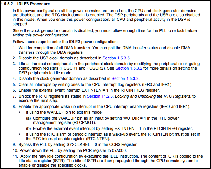
I am planning to execute processing according to the IDLE 3 procedure described in the following document(SPRUH16B).


However, it seems that disabling the CPU domain is missing compared with CSL's sample software(\\c55_csl_3.08\ccs_v6.x_examples\power\CSL_PowerManagement_IDLE3_Example\csl_power_management_idle3_example.c).
For example, disabling the system clock by PCGCR1.SYSCLKDIS and setting the CPU domain by idle configuration register (ICR) exist in the CSL sample.
Which procedure is correct?

If the system clock is disabled by SYSCLKDIS=1, there is a phenomenon that returning to IDLE3 sometimes does not return normally when repeating Enter / Return to IDLE3. So, is it impossible to disable the system clock?


Best regards,
H.U

  • Hi H.U,

    CSL_PowerManagement_IDLE3_Example demo works properly but I'll check for SYSCLKDIS state.

    BR
    Tsvetolin Shulev
  • Hi Tsvetolin Shulev,

    Thanks for the reply.
    My customer is having this problem on their board, please solve the problem immediately.
    Hope to hear from you soon.

    Best regards,
    H.U

  • H.U,

    Here are some clarifications about SYSCLKDIS bit field:
    When the system master clock is disabled (SYSCLKDIS=1), the external interrupt pins (INT0 and INT1) will be asynchronously latched and held low while the clocks are re-enabled.
    Once the clocks are re-enabled, the DSP will latch the interrupt in the IFR.
    Setting the WAKEUP pin high enables the system clock. Since the WAKEUP pin is used to re-enable the system clock, the WAKEUP pin must be low to disable the system clock.
    For more details about available methods for changing clock and IDLE3 (Standby mode) power configuration please refer to Table 1-34 of TMS320C5517 TRM at:
    www.ti.com/.../spruh16b.pdf
    Also I check again CSL_PowerManagement_IDLE3_Example demo and if no one of conditions described in Table 1-34 not appear the system stay endless in idle.

    BR
    Tsvetolin Shulev
  • Hi Tsvetolin Shulev,

    For customers' actual use cases, the RTC and WAKEUP pins are not used and only INT0 is used as the wakeup source.
    Please tell me the correct IDLE3 procedure in this case.

    and, In the CSL_PowerManagement_IDLE3_Example demo, it is programmed to control the ICR register, but I think this operation is unnecessary.

    CSL_IDLECTRL_REGS->ICR |= (CSL_IDLE_ICR_HWAI_MASK | CSL_IDLE_ICR_CPUI_MASK );


    I've heard from TI's local FAE that you could reproduce this problem with your EVM.
    Could you tell me about the root cause and solution?

    Best regards,
    H.U

  • Hi Tsvetolin Shulev,

    We are in a big hurry for this issue, because, the customer products are already shipped to the market.
    We must solve this problem immediately. Please get back to me as soon as possible. We need your help!

    Best regards,
    H.U

  • H.U,

    Could you please provide responses to the following?:

    - Bits 3 and 2 of the IFR0 and IER0 bits must be set to 1 to enable interrupts from INT1 and INT0, respectively. Are they set?

    - Is the pin CVDDRTC powered on?
    From the TRM, the CVDDRTC pin must always be powered by an external power source even though RTC
    is not used. None of the on-chip LDOs can power CVDDRTC.

    - Could you please provide a code snippet of the ISR routine for INT0?

    - What interrupts are present before you go into IDLE3?

    - Can you connect to the DSP via JTAG after INT0 is applied? Asking this in case you are able to poke registers to see the state of the DSP.

    Lali

  • Hi Lali,

    Lalindra Jayatilleke said:

    - Bits 3 and 2 of the IFR0 and IER0 bits must be set to 1 to enable interrupts from INT1 and INT0, respectively. Are they set?


    Yes, they use only INT0 setting.


    Lalindra Jayatilleke said:

    - Is the pin CVDDRTC powered on?
    From the TRM, the CVDDRTC pin must always be powered by an external power source even though RTC
    is not used. None of the on-chip LDOs can power CVDDRTC.

    Yes, the CVDDRTC of their board is powered by external power source.


    Lalindra Jayatilleke said:

    - Could you please provide a code snippet of the ISR routine for INT0?

    The INT0 interrupt routine only sets the user flag.
    Reconfiguration such as PLL is carried out after returning from the INT0 interrupt processing necessary for restoration.


    /*----------------------------------------------*/
    /* Power Save WakeUp ISR */
    /*----------------------------------------------*/

    interrupt void int0_isr(void)
    {
    user_flag = 1;
    }


    Lalindra Jayatilleke said:

    - What interrupts are present before you go into IDLE3?

    Interrupts other than INT0 are disabled.

    Lalindra Jayatilleke said:

    - Can you connect to the DSP via JTAG after INT0 is applied? Asking this in case you are able to poke registers to see the state of the DSP.


    Yes, which register should we observe?


    Best Regards,
    H.U

  • H.U,

    Please find attached a CCS project where we were able to wake-up the core by toggling INT0 on the EVM5517.

    We did not observe the problem that you are seeing.

    Please check the code.

    This is a log of the console output by running this example. Its based on the C55x CSL v3.08

    CSL INT0 WAKEUP TEST
    
    Disabling USB Clk domain
    
    Disabling Clk to all preipherals except Sysclk to clk generator
    
    Ground TP8 on EVM5517 to trigger INT0 Interrupt and wake-up core. Going to sleep....zzzzzzzz
    
    INT0 Interrupt has been generated
    
    Sysclk and PLL turned back ON
    
    Executing IDLE instruction next 
    INT0 Interrupt has been generated
    
    Sysclk and PLL turned back ON
    
    CSL INT0 TESTS COMPLETED
    

    Lali

    /cfs-file/__key/communityserver-discussions-components-files/791/3377.CSL_5F00_PowerManagement_5F00_IDLE3_5F00_INT0_5F00_Example.zip

  • Hi Lali,


    Thank you for your kindly support!

    In customer's environment this problem sometimes occurs when repeating IDLE3 mode. Are you conducting a transition to IDLE 3 mode repeatedly?
    It seems that your program is  performing IDLE3 mode only once.

    Best Regards,
    H.U

  • H.U,

    I'm looking into this and will get back to you.

    Lali
  • H.U, 

    Yes, I tested with repeated IDLE3 to wake-up. I have attached a video of the test that was done. You will notice a part of the video where the the board was in IDLE3 for 10 mins and then woken up.

    I wonder if the problem has something to so with the disabling of the USB clock domain?

    In my example as you may follow on the video, I had to restart the program after disabling the clock domain.

    /cfs-file/__key/communityserver-discussions-components-files/791/2063.INT0_5F00_demo.mp4

     Lali

  • Hi Lali,

    Thank you for your information.
    I will ask the customer if the problem will be reproduced in the way that you presented and get back to you.

    Best Regards,
    H.U