Tool/software: Code Composer Studio
Hi TI engineer
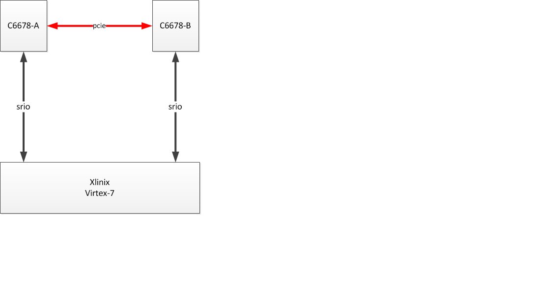
We use SRIO and PCIE of C6678 in our application.It seems that sometimes the link of these ports can't be build successfuly after power. The link is like this:
And the configuration is like this:
1. srio : 4x 5.0G Baud per lane
2.pcie 2x 5.0G Baud per lane
Error description:
1. For srio,the link between C6678-A/B and Virtex-7 can't be built, the regs 0x0290b158 is kept in 0x00000001;
2.For pcie,the link between C6678 A and B can't be built. The regs like this:
We check the regs cmd_status(0x21800004) and Debug 0 Register(0x21801728) , find it like this:
| Regs description | value (right) for C6678-A/B | value(wrong) for C6678-A | value(wrong) for C6678-B |
| Command Status Register bit 3:1(POSTED_WR_EN IB_XLT_EN OB_XLT_EN) | 0x7 | 0x0 | 0x4 |
| Debug 0 Register bit 4:0 LTSSM_STATE | 0x11 | 0x00 | unstable,keep changing |
More description:
It seems that when this happen, I only need to initilize it again, the link will be built most of time.But we still want to know how this happen,and if there is any unproper operation in our code.The code to init the port has been attached.You could check it. Thank you very much.
int KeyStone_PCIE_Init(KeyStone_PCIE_Config * pcie_cfg, CSL_Uint64 timeover)
{
	//soft reset PCIE if it is already in use
	if ((CSL_PSC_getPowerDomainState(CSL_PSC_PD_PCIEX) == PSC_PDSTATE_ON) &&
	   		(CSL_PSC_getModuleState (CSL_PSC_LPSC_PCIEX) == PSC_MODSTATE_ENABLE))
	{
		// Disable PCIE before reconfiguring
		KeyStone_PCIE_soft_reset();	//soft reset PCIE if it is already enabled
	}

	//enable PCIE power and clock domain
	KeyStone_enable_PSC_module(CSL_PSC_PD_PCIEX, CSL_PSC_LPSC_PCIEX);

	/*Set PCIESSMODE[1:0] in the device level register BOOT_REG0/DEVSTAT in KeyStone 1,
	or DEVCFG in KeyStone 2*/
	boot_cfg_regs->BOOT_REG0= (boot_cfg_regs->BOOT_REG0
 		&(~CSL_BOOTCFG_BOOT_REG0_PCIESS_MODE_MASK))
 		|(pcie_cfg->PcieMode<<CSL_BOOTCFG_BOOT_REG0_PCIESS_MODE_SHIFT);

	/*Set the DIR_SPD bit to 1 in the PL_GEN2 register during the
	initialization can switch the PCIe link speed
	mode from Gen1 (2.5Gbps) to Gen2 (5.0Gbps).*/
 	if(5.f==pcie_cfg->serdes_cfg.linkSpeed_GHz)
 		gpPCIE_CAP_implement_regs->PL_GEN2 |= CSL_PCIE_CFG_SPACE_ENDPOINT_PL_GEN2_DIR_SPD_MASK;
 	else
 		gpPCIE_CAP_implement_regs->PL_GEN2 &= ~CSL_PCIE_CFG_SPACE_ENDPOINT_PL_GEN2_DIR_SPD_MASK;

 	gpPCIE_CAP_implement_regs->PL_GEN2 = (gpPCIE_CAP_implement_regs->PL_GEN2&(~(CSL_PCIE_CFG_SPACE_ENDPOINT_PL_GEN2_LN_EN_MASK)))
		|(pcie_cfg->serdes_cfg.numLanes<<CSL_PCIE_CFG_SPACE_ENDPOINT_PL_GEN2_LN_EN_SHIFT);

 	if(pcie_cfg->serdes_cfg.tx_cfg)
	{
	 	gpPCIE_CAP_implement_regs->PL_GEN2 = (gpPCIE_CAP_implement_regs->PL_GEN2&(~(CSL_PCIE_CFG_SPACE_ENDPOINT_PL_GEN2_CFG_TX_SWING_MASK
	 		|CSL_PCIE_CFG_SPACE_ENDPOINT_PL_GEN2_DEEMPH_MASK)))
			|(pcie_cfg->serdes_cfg.tx_cfg->swing<<CSL_PCIE_CFG_SPACE_ENDPOINT_PL_GEN2_CFG_TX_SWING_SHIFT)
			|(pcie_cfg->serdes_cfg.tx_cfg->EP_de_emphasis<<CSL_PCIE_CFG_SPACE_ENDPOINT_PL_GEN2_DEEMPH_SHIFT);

		gpPCIE_CAP_implement_regs->LINK_CTRL2= (gpPCIE_CAP_implement_regs->LINK_CTRL2&(~(CSL_PCIE_CFG_SPACE_ENDPOINT_LINK_CTRL2_DE_EMPH_MASK
	 		|CSL_PCIE_CFG_SPACE_ENDPOINT_LINK_CTRL2_TX_MARGIN_MASK|CSL_PCIE_CFG_SPACE_ENDPOINT_LINK_CTRL2_SEL_DEEMPH_MASK)))
			|(pcie_cfg->serdes_cfg.tx_cfg->de_emphasis<<CSL_PCIE_CFG_SPACE_ENDPOINT_LINK_CTRL2_DE_EMPH_SHIFT)
			|(pcie_cfg->serdes_cfg.tx_cfg->tx_margin<<CSL_PCIE_CFG_SPACE_ENDPOINT_LINK_CTRL2_TX_MARGIN_SHIFT)
			|(pcie_cfg->serdes_cfg.tx_cfg->EP_5G_de_emphasis<<CSL_PCIE_CFG_SPACE_ENDPOINT_LINK_CTRL2_SEL_DEEMPH_SHIFT);
	}

	/*configure Serdes loopback mode according to PCIE loopback mode*/
	if((PCIE_PHY_LOOPBACK==pcie_cfg->loop_mode))
	{
		pcie_cfg->serdes_cfg.loopBack = SERDES_LOOPBACK_ENABLE;
	}
	else
	{
		pcie_cfg->serdes_cfg.loopBack = SERDES_LOOPBACK_DISABLE;
	}

	KeyStone_PCIE_Serdes_init(&pcie_cfg->serdes_cfg);

	if(!PcieWaitPllToLock(timeover))
		return DRIVER_RESULT_PLL_UNLOCK;

	/*Disable link training by de-asserting the LTSSM_EN bit in the PCIESS
	Command Status Register (CMD_STATUS[LTSSM_EN]=0). Upon reset, the
	LTSSM_EN is de-asserted automatically by hardware.*/
	gpPCIE_app_regs->CMD_STATUS &= ~CSL_PCIESS_APP_CMD_STATUS_LTSSM_EN_MASK;

	if(pcie_cfg->bCommon_clock)
		gpPCIE_CAP_implement_regs->LINK_STAT_CTRL |=
			CSL_PCIE_CFG_SPACE_ENDPOINT_LINK_STAT_CTRL_COMMON_CLK_CFG_MASK;

	KeyStone_PCIE_Internal_Bus_Init(pcie_cfg->bus_cfg);

	KeyStone_PCIE_Interrupt_Init(pcie_cfg->interrupt_cfg, pcie_cfg->address_width);


	/*Initiate link training can be initiated by asserting LTSSM_EN bit in the
	CMD_STATUS register (CMD_STATUS[LTSSM_EN]=1).*/
	gpPCIE_app_regs->CMD_STATUS |= CSL_PCIESS_APP_CMD_STATUS_LTSSM_EN_MASK;


	if(PCIE_PHY_LOOPBACK == pcie_cfg->loop_mode)
	{
		/*DETECT state (0 and 1) should be skipped in loopback mode
		by forcing link state to start with POLL_ACTIVE state (2) */
		gpPCIE_CAP_implement_regs->PL_FORCE_LINK |=
			CSL_PCIE_CFG_SPACE_ENDPOINT_PL_FORCE_LINK_FORCE_LINK_MASK
			|(LTSSM_STAT_POLL_ACTIVE
			 <<CSL_PCIE_CFG_SPACE_ENDPOINT_PL_FORCE_LINK_LNK_STATE_SHIFT);
	}

	if(!PcieWaitPortToLink(timeover))
		return DRIVER_RESULT_LINK_TIMEOUT;

	return 0;
}

/*Remote Configuration Transaction Setup,
select the bus, device and function number of the target*/
void KeyStone_PCIE_remote_CFG_setup(PCIE_Remote_CFG_SETUP * cfg_setup)
{
	gpPCIE_app_regs->CFG_SETUP=
		(cfg_setup->config_type<<CSL_PCIESS_APP_CFG_SETUP_CFG_TYPE_SHIFT)
		|(cfg_setup->config_bus<<CSL_PCIESS_APP_CFG_SETUP_CFG_BUS_SHIFT)
		|(cfg_setup->config_device<<CSL_PCIESS_APP_CFG_SETUP_CFG_DEVICE_SHIFT)
		|(cfg_setup->config_function<<CSL_PCIESS_APP_CFG_SETUP_CFG_FUNC_SHIFT);
}


void PcieCfgParamSet(
		PCIE_Mode mode,
		PcieBaudRate baudrate,
		KeyStone_PCIE_Config* pPcieCfg
)
{
	//clear all configuration data structure
	memset(&g_pcieIntCfg,	0, sizeof(g_pcieIntCfg));
	memset(pPcieCfg,		0, sizeof(KeyStone_PCIE_Config));


	pPcieCfg->PcieMode = mode;


	pPcieCfg->serdes_cfg.inputRefClock_MHz = 100;


	if(baudrate == Pcie_2500M)
		pPcieCfg->serdes_cfg.linkSpeed_GHz = 2.5;
	else
		pPcieCfg->serdes_cfg.linkSpeed_GHz = 5;


	pPcieCfg->serdes_cfg.numLanes = 2;
	pPcieCfg->serdes_cfg.loopBandwidth = SERDES_PLL_LOOP_BAND_MID;
	pPcieCfg->serdes_cfg.txInvertPolarity = SERDES_TX_NORMAL_POLARITY;
	pPcieCfg->serdes_cfg.rxInvertPolarity = SERDES_RX_NORMAL_POLARITY;
	pPcieCfg->serdes_cfg.rxEqualizerConfig = SERDES_RX_EQ_ADAPTIVE;
	pPcieCfg->serdes_cfg.rxCDR				= SERDES_RX_CDR_2;
	pPcieCfg->serdes_cfg.rxLos 				= SERDES_RX_LOS_DISABLE;
	pPcieCfg->serdes_cfg.rxAlign			= SERDES_RX_ALIGNMENT_DISABLE;
	pPcieCfg->serdes_cfg.inputRefClock_MHz	= 156.25;


	pPcieCfg->loop_mode = PCIE_LOOPBACK_DISABLE;
	pPcieCfg->address_width = PCIE_ADDRESS_32_BITS;


	g_pcieIntCfg.MSI_rx_enable_mask = 0xFFFFFFFF;
	g_pcieIntCfg.Err_rx_enable = TRUE;
	g_pcieIntCfg.PMRST_rx_enable = TRUE;
    g_pcieIntCfg.number_tx_MSI = PCIE_32_MSI;
    pPcieCfg->interrupt_cfg = &g_pcieIntCfg;


    pPcieCfg->rc_cfg = NULL;
    pPcieCfg->inbound_memory_regions = NULL;
    pPcieCfg->outbound_memory_regions = NULL;
    pPcieCfg->bus_cfg = NULL;
    pPcieCfg->error_cfg = NULL;
}


int keystone_PCIE_RC_MSI_allocate(void)
{
	Uint32 regVal,MsgEnVal;

	regVal = gpPCIE_remote_EP_Regs->MSI_CAP;

	if(0==(regVal&CSL_PCIE_CFG_SPACE_ENDPOINT_MSI_CAP_MSI_EN_MASK))
		return -3;	//MSI is not enabled in this device

	MsgEnVal = PcieGetMsgEn(regVal);

	//write the number of the allocated vectors for the EP
	gpPCIE_remote_EP_Regs->MSI_CAP = (regVal&(~CSL_PCIE_CFG_SPACE_ENDPOINT_MSI_CAP_MULT_MSG_EN_MASK))
		|(MsgEnVal<<CSL_PCIE_CFG_SPACE_ENDPOINT_MSI_CAP_MULT_MSG_EN_SHIFT);

	//write the PCIE address for EP to write to generate MSI
	gpPCIE_remote_EP_Regs->MSI_LOW32 = gpPCIE_RC_regs->BAR[0] +
			(((Uint32)&gpPCIE_app_regs->MSI_IRQ)-(Uint32)gpPCIE_app_regs);
	gpPCIE_remote_EP_Regs->MSI_UP32 = 0;

	gpPCIE_remote_EP_Regs->MSI_DATA = (1<<MsgEnVal);

	return 0;
}

void PcieAddrMapInit(PCIE_Mode mode)
{
	int region = 0;

	if(PCIE_RC_MODE == mode)
	{
		//bar mask cfg
		gpPCIE_app_regs->CMD_STATUS |= CSL_PCIESS_APP_CMD_STATUS_DBI_CS2_MASK;
		gpPCIE_RC_regs->BAR[0] = 0x007FFFFF;/*8M*/
		gpPCIE_RC_regs->BAR[1] = 0x07FFFFFF;/*128M*/
		gpPCIE_app_regs->CMD_STATUS &= CSL_PCIESS_APP_CMD_STATUS_DBI_CS2_MASK;

		gpPCIE_RC_regs->STATUS_COMMAND |= 0x146;
		gpPCIE_RC_regs->DEV_STAT_CTRL |= 0xF;
		gpPCIE_RC_regs->PCIE_ACCR |= 0x1E0;

		//outbound cfg
		gpPCIE_app_regs->OB_SIZE = PCIE_OB_SIZE_8MB;
		for(region = 0;region < 32;region++)
		{
			gpPCIE_app_regs->OUTBOUND_TRANSLATION[region].OB_OFFSET_INDEX
			= 0x70000001 + 0x800000*region;
			gpPCIE_app_regs->OUTBOUND_TRANSLATION[region].OB_OFFSET_HI = 0;
		}
		gpPCIE_app_regs->CMD_STATUS |= CSL_PCIESS_APP_CMD_STATUS_OB_XLT_EN_MASK;

		//bar cfg
		gpPCIE_RC_regs->BAR[0] = 0x90000000;
		gpPCIE_RC_regs->BAR[1] = 0x98000000;

		//inbound cfg
		gpPCIE_app_regs->INBOUND_TRANSLATION[0].IB_BAR=0;
		gpPCIE_app_regs->INBOUND_TRANSLATION[0].IB_START_LO = 0x90000000;
		gpPCIE_app_regs->INBOUND_TRANSLATION[0].IB_START_HI = 0;
		gpPCIE_app_regs->INBOUND_TRANSLATION[0].IB_OFFSET = 0;

		gpPCIE_app_regs->INBOUND_TRANSLATION[1].IB_BAR=1;
		gpPCIE_app_regs->INBOUND_TRANSLATION[1].IB_START_LO = 0x98000000;
		gpPCIE_app_regs->INBOUND_TRANSLATION[1].IB_START_HI = 0;
		gpPCIE_app_regs->INBOUND_TRANSLATION[1].IB_OFFSET = 0x0c000000;

		gpPCIE_app_regs->INBOUND_TRANSLATION[2].IB_BAR=0;
		gpPCIE_app_regs->INBOUND_TRANSLATION[2].IB_START_LO = 0x98400000;
		gpPCIE_app_regs->INBOUND_TRANSLATION[2].IB_START_HI = 0;
		gpPCIE_app_regs->INBOUND_TRANSLATION[2].IB_OFFSET = 0x80000000;

		gpPCIE_app_regs->INBOUND_TRANSLATION[3].IB_BAR=0;
		gpPCIE_app_regs->INBOUND_TRANSLATION[3].IB_START_LO = 0;
		gpPCIE_app_regs->INBOUND_TRANSLATION[3].IB_START_HI = 0;
		gpPCIE_app_regs->INBOUND_TRANSLATION[3].IB_OFFSET = 0;
		gpPCIE_app_regs->CMD_STATUS |= CSL_PCIESS_APP_CMD_STATUS_IB_XLT_EN_MASK;
	}
	else
	{
		//bar mask cfg
		gpPCIE_app_regs->CMD_STATUS |= CSL_PCIESS_APP_CMD_STATUS_DBI_CS2_MASK;
		gpPCIE_EP_regs->BAR[0] = 0x003FFFFF;/*4M*/
		gpPCIE_EP_regs->BAR[1] = 0x07FFFFFF;/*128M*/
		gpPCIE_app_regs->CMD_STATUS &= CSL_PCIESS_APP_CMD_STATUS_DBI_CS2_MASK;

		gpPCIE_EP_regs->STATUS_COMMAND |= 0x146;
		gpPCIE_EP_regs->DEV_STAT_CTRL |= 0xF;
		gpPCIE_EP_regs->PCIE_ACCR |= 0x1E0;

		//outbound cfg
		gpPCIE_app_regs->OB_SIZE = PCIE_OB_SIZE_8MB;
		for(region = 0;region < 32;region++)
		{
			gpPCIE_app_regs->OUTBOUND_TRANSLATION[region].OB_OFFSET_INDEX
			= 0x90000001 + 0x800000*region;
			gpPCIE_app_regs->OUTBOUND_TRANSLATION[region].OB_OFFSET_HI = 0;
		}
		gpPCIE_app_regs->CMD_STATUS |= CSL_PCIESS_APP_CMD_STATUS_OB_XLT_EN_MASK;

		//bar cfg
		gpPCIE_EP_regs->BAR[0] = 0x70000000;
		gpPCIE_EP_regs->BAR[1] = 0x78000000;

		//inbound cfg
		gpPCIE_app_regs->INBOUND_TRANSLATION[0].IB_BAR=0;
		gpPCIE_app_regs->INBOUND_TRANSLATION[0].IB_START_LO = 0x70000000;
		gpPCIE_app_regs->INBOUND_TRANSLATION[0].IB_START_HI = 0;
		gpPCIE_app_regs->INBOUND_TRANSLATION[0].IB_OFFSET = 0;��

		gpPCIE_app_regs->INBOUND_TRANSLATION[1].IB_BAR=1;
		gpPCIE_app_regs->INBOUND_TRANSLATION[1].IB_START_LO = 0x78000000;
		gpPCIE_app_regs->INBOUND_TRANSLATION[1].IB_START_HI = 0;
		gpPCIE_app_regs->INBOUND_TRANSLATION[1].IB_OFFSET = 0x0c000000;

		gpPCIE_app_regs->INBOUND_TRANSLATION[2].IB_BAR=0;
		gpPCIE_app_regs->INBOUND_TRANSLATION[2].IB_START_LO = 0x78400000;
		gpPCIE_app_regs->INBOUND_TRANSLATION[2].IB_START_HI = 0;
		gpPCIE_app_regs->INBOUND_TRANSLATION[2].IB_OFFSET = 0x80000000;

		gpPCIE_app_regs->INBOUND_TRANSLATION[3].IB_BAR=0;
		gpPCIE_app_regs->INBOUND_TRANSLATION[3].IB_START_LO = 0;
		gpPCIE_app_regs->INBOUND_TRANSLATION[3].IB_START_HI = 0;
		gpPCIE_app_regs->INBOUND_TRANSLATION[3].IB_OFFSET = 0;
		gpPCIE_app_regs->CMD_STATUS |= CSL_PCIESS_APP_CMD_STATUS_IB_XLT_EN_MASK;
	}
}
