This thread has been locked.

If you have a related question, please click the "Ask a related question" button in the top right corner. The newly created question will be automatically linked to this question.

TVP5147M1 in weak signal mode on DM8148 evm

Other Parts Discussed in Thread: TVP5147M1, TVP5147

Because TVP5147M1 output Y[2:9] is connected to VIN1[8:16] on the 8148EVM, 10bit embeded sync mode cannot be used for video capture. I am now using  20 bit discrete sync mode of TVP5147M1. But I meet problems below:

1) 5147M1 can't always get sync locked with PAL camera signal. Sometime it can get sync locked and othertime it can't.

2)   When 5147M1 get sync  locked with camera, weak singal mode is detected, video data is not correct. So I doubt that 5147 is not really sync with camera.

Below are registers values of TVP5147M1

tvp514x 3-005c: Standard set to: PAL
tvp514x 3-005c: Reg(0x00): 0x05
tvp514x 3-005c: Reg(0x01): 0x0F
tvp514x 3-005c: Reg(0x02): 0x02
tvp514x 3-005c: Reg(0x03): 0x30
tvp514x 3-005c: Reg(0x04): 0x03
tvp514x 3-005c: Reg(0x05): 0x10
tvp514x 3-005c: Reg(0x06): 0x00
tvp514x 3-005c: Reg(0x07): 0x00
tvp514x 3-005c: Reg(0x08): 0x00
tvp514x 3-005c: Reg(0x09): 0x80
tvp514x 3-005c: Reg(0x0A): 0x80
tvp514x 3-005c: Reg(0x0B): 0x80
tvp514x 3-005c: Reg(0x0C): 0x00
tvp514x 3-005c: Reg(0x0D): 0x00
tvp514x 3-005c: Reg(0x0E): 0x04
tvp514x 3-005c: Reg(0x10): 0x80
tvp514x 3-005c: Reg(0x11): 0x80
tvp514x 3-005c: Reg(0x12): 0x80
tvp514x 3-005c: Reg(0x14): 0x80
tvp514x 3-005c: Reg(0x16): 0x5F
tvp514x 3-005c: Reg(0x17): 0x00
tvp514x 3-005c: Reg(0x18): 0x2F
tvp514x 3-005c: Reg(0x19): 0x03
tvp514x 3-005c: Reg(0x1A): 0x07
tvp514x 3-005c: Reg(0x1B): 0x00
tvp514x 3-005c: Reg(0x1C): 0x47
tvp514x 3-005c: Reg(0x1D): 0x00
tvp514x 3-005c: Reg(0x1E): 0x01
tvp514x 3-005c: Reg(0x1F): 0x00
tvp514x 3-005c: Reg(0x20): 0x04
tvp514x 3-005c: Reg(0x21): 0x00
tvp514x 3-005c: Reg(0x22): 0x6F
tvp514x 3-005c: Reg(0x23): 0x02
tvp514x 3-005c: Reg(0x24): 0x18
tvp514x 3-005c: Reg(0x25): 0x00
tvp514x 3-005c: Reg(0x32): 0x00
tvp514x 3-005c: Reg(0x33): 0x01
tvp514x 3-005c: Reg(0x34): 0x13
tvp514x 3-005c: Reg(0x35): 0xEE
tvp514x 3-005c: Reg(0x36): 0xAF
tvp514x 3-005c: Reg(0x37): 0xFF
tvp514x 3-005c: Reg(0x38): 0xFF
tvp514x 3-005c: Reg(0x39): 0x01
tvp514x 3-005c: Reg(0x3A): 0x6E
tvp514x 3-005c: Reg(0x3B): 0xD8
tvp514x 3-005c: Reg(0x3C): 0x00
tvp514x 3-005c: Reg(0x3D): 0x00
tvp514x 3-005c: Reg(0x3F): 0x02
tvp514x 3-005c: MBUS_FMT: Width - 720, Height - 576.

.

  • Why AGC value is 0 from 0x3C-0x3D(minimal AGC) while weak signal is detected by 5147m1?

    Why 5147m1 can't keep sync with camera according to value of 0x3A? It's value is 0x70 or something like this.

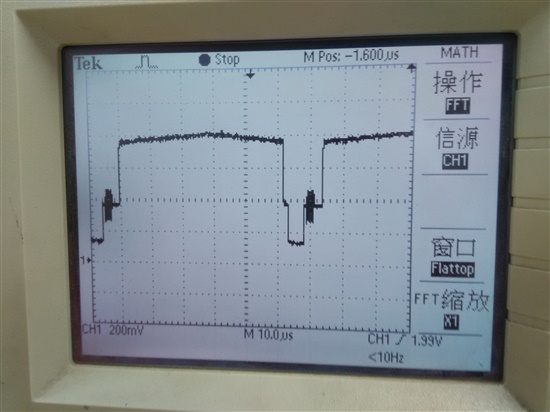
  • I would suggest you get the video waveform form TVP5147's input pin and  check how bad the signal is.

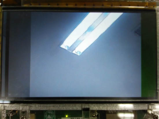
  • Input signal is correct, below is signal wave from camera. I think it must be caused by some register setting error. 

    below is input signal wave.

  • Have you changed any registers from their default other than the output enables?

    Are you using firmware patch code or the default ROM code of the TVP5141M1?

    BR,

    Steve

  • Hi,

    5147M1 can't always get sync locked with PAL camera signal. Sometime it can get sync locked and othertime it can't.

    I have come across a similar case,  kind of weird workaround may be it might help you, you need to rub the crystal near to tvp514x chip (Y1) to charge (may be for a min) and then start your application.

    Thanks,

    --Prabhakar Lad

  • If you need to do that then your crystal circuit is not loaded correctly.

    In this case I suggest you look at the output clock and measure it with a frequency counter (note an oscilloscope is not accurate enough for this test).

    You then need to 'tune' the crystal load capacitors until the frequency is within a few PPM of 27MHz.

    It may also be necessary to add a resistor in parallel with the crystal in the 1M range to make the oscillator stable.

    This is all crystal dependent. You need to make sure that you are following the crystal manufacturer's guidelines for loading etc...

    BR,

    Steve

  • I am using capture mode of 20-bit discrete sync mode.

    So the output DATACLK shoud be 13.5MHz I think.

    But the measured DATACLK is 6.75MHz. Is it a correct clock input to dm8148?

    In interlaced scanning, 6.75MHz is a correct frequency value?

  • AGC register value I posted before was not correctly read.

    It's reading is:

    tvp514x 3-005c: Reg(0x3C): 0x6D
    tvp514x 3-005c: Reg(0x3D): 0x06

    so only fine AGC is used, 0x66D is lower than 1000,0000,0000b,it may change a little but always lower than 1000000000000b,then I guess the input signal voltage is larger than 1Vp-p. But from register 0x3A, weak signal is detected. I can not make it clear what this situation means.

  • I think I am using default ROM code ot TVP5147M1. I didn't update 5147 firmware on EVM. 

  • No, the clock should be either 27MHz for 8 bit output mode or 13.5MHz for 16 bit output.

    Can you monitor the crystal to see what frequency it is oscillating at and also that it is stable. Note, often when you put the scope probes on the crystal it will suddenly oscillate at a different frequency so make sure to monitor the PClk out at the same time to see if that changes.

    It sounds like your crystal is not loaded correctly hence not oscillating correctly.

    Try different crystals with different load capacitor requirements too.

    BR,

    Steve

  • OK, I am not asking about the EVM firmware although if you are simply using the out of the box DM code then you would need to check with the SDK/RDK team to see if your version of the Kernel/TVP driver downloads patch code to the TVP. I doubt it does though since it is not necessary in most cases.

    The TVP51xx family of devices have the ability to update the code which is contained inside the TVP. This is NOT permanent so when power is removed it is necessary to re-download the firmware through I2C on next power up if desired.

    This firmware is not necessary in most cases and the internal ROM code usually covers 95% of use cases. The patch code is only necessary to download if the issues it fixes/features it adds are actually required by your application. As I say though 95% of use cases do not require this.

    BR,

    Steve

  • Hi

        The cystal is measused with no clock output.

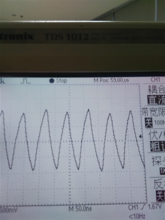
        Even when I disconnect the input video from EVM board, I can still measure from terminal 40(DATACLK) of TVP5147M1 a wave frequency of nearly 13.5MHz. After reboot the EVM board, I set 5147m1's registgers following example 1 in 5147M1 data manual.

    terminal 40 of 5147m1:

  • Can you please clarify the following...

    Are you saying that with no video input the PClk output is stable at 13.5MHz but when you then connect a video signal it changes to 6.75MHz?


    I suggest leaving ALL registers at their default and only changing the output enable and, if necessary, the output format.

    BR,

    Steve

  • Hi

    I mean that after initialization of 5147 with no video input and 20-bit discrete sync output format, the PCLK output is 6.75MHz, after initialization of 5147 with no video input and 10-bit embedded sync output format, the PCLK output is 13.5MHz.

    No matter what output format is, the PCLK frequency is half value of a correct one. Obviously, the PCLK has nothing to do with 5147 has gotten sync locked with input video or not.

    From the crystal terminal, no clock has been measured. So I think the output PCLK is selt activated? I have changed a new crystal with 14.31818MHz, but the phenomena I mentioned above keep unchanged. 

    Now I don't know if something unusal occured in the chip TVP5147M1 or the chip has been damaged?

  • Hi

    PCLK is half value of a correct one no matter with or without input video.

    I set the output format to 10-bit embedded sync mode and 20-bit discrete sync mode respectively, the corresponding PCLK is 13.5M and 6.5M. With input video or not has no effect on the PCLK frequency.

  • This really sounds like a crystal issue.

    Do you have a clock generator that can generate a 14.31818MHz signal? If so then remove the crystal and supply this to the XI input (XTAL1)to see if you get the same /2 output DataClk.

    Even with no video input there should always be a valid output DataClk. This is so that when there is no video source input that the output data stream is still standards compliant.

    Once the TVP locks to the incoming video the data clock will then track the source video, but until then it should free-wheel at the correct frequency for the output format.

    Are all your power supplies clean and at the correct levels (both ground and power test points measured at the TVP)?

    Did you provide a good reset signal pulse?

    Didi you ensure that all I2C activity starts after the reset period?

    Is the crystal oscillating at the correct frequency? (note, adding capacitance of the scope probe can, in some cases, suddenly make the crystal oscillate at a different and/or correct frequency, so I suggest measuring both data clock and crystal at the same time with different scopes so you can see any changes in behavior). Use the lowest possible scope probe capacitance, which is usually the 10x mode.

    If you think there might be the possibility you have damaged the TVP then do you have another board and/or TVP you can try?

    BR,

    Steve

  • Hi

    I have replace the passive crystal with an active crystal, and the output dataclk is correct. It's 13.5MHz when I am using 20-bit discrete sync mode. 

    I am using VPS_CAPT_VIDEO_CAPTURE_MODE_SINGLE_CH_NON_MUX_DISCRETE_SYNC_HSYNC_VSYNC mode as dm8148 capture mode.But the captured video data is still not correct. The HSYNC keeps jitttering while AVID keeps relatively stable 15.625KHz observed from oscilloscope.

  • Hi

    Using 20-bit discrete sync mode, I can get video captured from VIP1 Port A and show it on the LCD of 8148 EVM but the video is not correct.

    I am using HSYNC and VSYNC, I think apart from HSYNC and VSYNC, FID is needed to keep sync with tvp5147.

    I want to make it clear that in case of discrete sync mode, FID is needed for video capturing from DM8148 or not.

    On the expansion IO board, FID is not connected to DM8148.

  • Yes, if using discrete syncs then FID is required.

    I suggest switching to embedded syncs.

    BR,

    Steve

  • Hi

    I am using 16-bit discrete sync mode.

    TVP5147 can't support 16-bit embedded sync mode,it only support 8-bit embeded sync mode.

    Because TVP5147 Y output terminals are connected to VIP1 port A bit8-bit15 of DM8148, the captured video data keep being zero if using 8-bit embedded sync mode(the data is coming from C output terminals).

    I can now get video displaying on LCD of EVM, but video data is not correct.

    It seems that only one field of video is correctly captured, the other field is not get sync locked by DM8148 VIN1 port A. 

  • Hi

    The two VSYNC of up and bottom fields are at different positions considering position of HSYNC.

    I am using V4L2 driver for video capture and display. From nowhere I can set the offset of two VSYNC of different fields on DM8148. From one field, I can see objects in the video, but the other field shows only as bars.

    Has the 16bit discrete sync mode capture with interlace scanning format video been verified? 


  • Hi,


    It is possible to capture from VIP PortB as well in the embedded sync mode, please check if data lines and pclk is correctly connected. Once it is confirmed to be connected correctly, you should be able to capture from the port B as well.


    Rgds,

    Brijesh

  • Hi

    Output data lines of tvp5147m1 are connected to VIN[1]A bit0-bit15 of DM8148 on the EVM board, in this condition, I can't use VIN[1] port B to capture interlace video.

    With VIN[1] port A, one can only use 16-bit mode because  the 8 output data lines is connected to bit8-bit15 of DM8148 VIN[1] port A when using 8-bit mode. 

    TVP5147m1 supports discrete mode only when it is configured  to work as 8-bit output.

  • Hi

    I have made a little progress.

    I can now capture one field internaced video and show it one LCD of dm8168 EVM correctly.

    But I can't get the other field video data so they all keeps zero.

    Below is my driver related settings.

    {
      .name = TVP5147_INST0,
      .board_info = {
       I2C_BOARD_INFO("tvp5147m1", 0x5c),
       .platform_data = &tvp5147_pdata,
      },
      .vip_port_cfg = {
       .ctrlChanSel = VPS_VIP_CTRL_CHAN_DONT_CARE,
       .ancChSel8b = VPS_VIP_ANC_CH_SEL_DONT_CARE,
       .pixClkEdgePol = VPS_VIP_PIX_CLK_EDGE_POL_RISING,
       .invertFidPol = 0,
       .embConfig = {
        .errCorrEnable = 1,
        .srcNumPos = VPS_VIP_SRC_NUM_POS_DONT_CARE,
        .isMaxChan3Bits = 0,
       },
       .disConfig = {
        .fidSkewPostCnt = 0,
        .fidSkewPreCnt = 0,
        .lineCaptureStyle = VPS_VIP_LINE_CAPTURE_STYLE_HSYNC,
        .fidDetectMode = VPS_VIP_FID_DETECT_MODE_PIN,
        .actvidPol = VPS_VIP_POLARITY_DONT_CARE,
        .vsyncPol =  VPS_VIP_POLARITY_LOW,
        .hsyncPol = VPS_VIP_POLARITY_LOW,
       }
      },
      .video_capture_mode = VPS_CAPT_VIDEO_CAPTURE_MODE_SINGLE_CH_NON_MUX_DISCRETE_SYNC_HSYNC_VSYNC,
          .video_if_mode = VPS_CAPT_VIDEO_IF_MODE_16BIT,//VPS_CAPT_VIDEO_IF_MODE_8BIT,
      .input_data_format = FVID2_DF_YUV422P,
     }

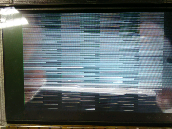
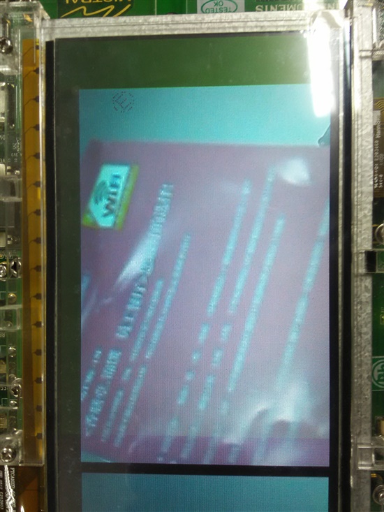
    The captured image:

  • From the captured video displaying on LCD of 8148 EVM, there are two exceptions:

    1) one field is correct and the other field keeps zero

    2) field does not keep sync with its counterpart field.

    So I doubt that 8148 has not handle VSYNC correctly because VSYNCs of the two fields are at different horizontal position and vertical lines. But this can't explain why one field vdieo data keeps zero.

    I have made a test, write the buffer wait to be filled by capture with data string 0,1,2,...,15,I found them have been overwritten.So two fields have written data into the buffer.

    8148 EVM has another problem, the FLD outputed by tvp5147 is connected to ground and not connected to 8148. On 8148 the FLD terminal is muxed with AVID and AVID of tvp5147 is connected to 8148 AVID/FLD terminal. So the FLD is not correctly used by 8148.

    I have setted the tvp5147 AVID as GPIO input and connected FLD outputed by 5147 to 8148 AVID/FLD terminal, but the result keeps the same with what I posted previously.  I think 8148 take the AVID/FLD terninal as AVID input by default and I just connect it with FLD, it would not take effect as FLD input. It shoud be setted as FLD input first. But because I have no 8148 register mannual I can't do this.


  • Hi

    We are blocked by the problem that one field video data keeps zero.

    Have anybody meet this before?

  • Previously I had asked two questions as below

    1) one field is correct and the other field keeps zero.

    2) field does not keep sync with its counterpart field.

    After I changed vertical sync mode from VSYNC to VBLK,question 2) has been resolved.

    Question 1) still keeps open. Anybody can make any suggestion? 

  • This is most likely not a TVP issue since it is not possible for the TVP to send a blank field.

    I cannot help on the processor side unfortunately so hopefully Brijesh can help.

    BR,

    Steve

  • VIP1 portA 16-bit discrete interlace video input, in this case, it can't be captured correctly.

    It seems 8148 use VBLK and ACTVID to sync with input video data, if one replace them with VSYNC/HSYNC, then vertical/horitontal sync can't be achieved.

    FID/ACTVID are muxed on terminal AA23, it can be set in software which input is on the terminal 0x48140B34.

    Using ACTVID, FID can't be used, the one field data lost(first two frames are correct, after that one field data lost every frame).

    Using FID, ACTVID can't be used, two fields can't keep horizontal sync with each other(two fields all have video data).  

    So it's last possibility that one can use ACTVID/VBLK, set FID come from VSYNC(not from PIN), but this mode I failed with one field video data lost. If using FID coming from PIN, what fidSkewPostCnt/fidSkewPreCnt are meaning is not clear. This has been the last hope but I failed too.

    Conclusion can be made that  VIP1 portA 16-bit discrete interlace video capture is not supported by DM8148, let alone on the dm8148 EVM. This EVM is really terrible.


  • From video captrued, I can see if using VSYNC/HSYNC, the blank period was captured(color displaying is black on left and up border).So ACTVID/VBLK must be used, otherwise the captured video can't keep sync with tvp5147 output.

    This part of software in SDK might not have been verified.

  • Hi,


    This is expected, when you use hsync/vsync mode of capture, it will also capture horz and vert blanking.

    If the FID is not connected, there is another way of detecting FID, by vsync skew, please refer to the VIP specs, it will give more details about this.


    Regards,

    Brijesh

  • Hi

    “VIP specs” is what I am interested in, but where can I got it?

    It will be a great favor if you can provide some information about it.

    I have tried with detecting FID from VSYNC skew, but it's still lost one field. It seems that FID detect didn't take effect.

    If FID auto detection is tested feasible, I will use HSYNC/VSYNC/ACTVID to capture the input interlace video.  

  • Hi,


    Why dont you connect FID line itself? It would easier and always correct if the FID input itself is available for the interlaced input.

    On which board you are trying? If this is catalog board, we were able to capture NTSC/PAL from TVP5147 on VIP PortB. There is some board modification required, but it is possible. If you confirm that is is catalog, i will share the changes required.


    Rgds,

    Brijesh

  • Hi

    Thanks for your reply so quickly. If I connect FID to AA23, then I am forced to use VPS_VIP_LINE_CAPTURE_STYLE_HSYNC to capture video line, this will lead the two field not aligned on horizontal direction.

    I am using Mistral IO board REV D + Mistral Base board REV D 

  • There is binaries included in the disk comes w/ your EVM.   There is test program for EVM+TVP5147

  • Hi,


    As i said, If you are using hsync stype of capture, you will have to crop horizontal blanking, because that will also get captured. This has nothing to do with FID pin. But it is not alignment issue.


    Rgds,

    Brijesh

  • "TVP5147m1 supports discrete mode only when it is configured  to work as 8-bit output." this is not true. ITU656 mode is definitely supported.

    I am fairly sure 16 bit embedded mode is supported too. You can also enable the discrete syncs in both 8 and 16 bit mode I believe but I am not 100% sure on the exact alignment when both sets of syncs are enabled.

    BR,

    Steve

  • OK, just re-read the statement and it can be interpreted in 2 ways !!. I thought you were saying 8 bit mode only supported discrete syncs but you were really saying discrete syncs is only supported in 8 bit mode.

    Either way, I think discrete syncs can actually be enabled in 8 bit and 16 bit. I will try to verify this though.

    BR,

    Steve

  • Hi

    Yes, "TVP5147m1 supports discrete mode only when it is configured  to work as 8-bit output." is my expression error. What I  meant to is 5147 support discrete mode with 16-bit output only(considering the Mistral EVM board).

    Because when setting 8-bit output, the Y component data lines are connected to VIP1 port A bit8-bit15 of dm8148 EVM, captured video data will be all zero(bit 0-bit7 of port A is connected with C component output data lines of 5147m1). So 8-bit output of 5147 can't be used currently considering the Mistral dm8148 EVM.

    There last option is 16-bit discrete sync mode. But with this mod, FID and AVID muxted on dm8148, I have found using HSYNC other than AVID, the two fields of captured video data can't keep horizontal alignment.  

  • Hi

    Sorry for my expression error.

    5147m1 itself can support :

      1) 8-bit embedded sync mode;

      2) 8-bit discrete sync mode;

      3) 16-bit discrete sync mode

    But considering the data line connection error of Mistral EVM board, only 16-bit can be used.

    So actually there is only one option left, it's 16-bit discrete sync mode.

    On the Mistral EVM, Y component output lines Y2-Y9 are connected to bit8-bit15 of VIN1 port A, C2-C9 are connected to bit0-bit7 of VIN1 portA. When using 8-bit output of 5147m1, all data is output on Y component.

    I have captured almost correct video data using option 3) with the exception that two fields not aligned on horizontal direction. This is a blocking problem currently we are confronting.

  • Can you share the image showing alignment issue? Also does this mean both the fields are getting captured?

    regards,

    brijesh

  • Hi

    I have already connect FID to DM8148 and set FID/AVID terminal AA23 input as FID and disabled tvp5147m1 AVID output.

  • It's weird.

    The image doesn't show in the post.

  • I could not see the picture completely, but i think there are some edges have steps on each line. Can you confirm the same?

    I think this could be because of the field inversion. Can you check if your decoder support field inversion and try it? If the artifacts are because of the field inversion, it will go away once you invert FID from the decoder.

    If i remember correctly, for PAL, the FID is always inverted and for NTSC, it is not inverted, so are you trying PAL input? Can you try NTSC first and check?


    Regards,

    Brijesh

  • Hi

    Thank you for your reply.

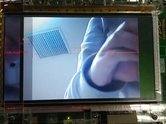
    The image showing on LCD is fully shot but is not very clear after cameraed.

    You can see left part of one field about 160 pixels of line segmentation shows black, after this the line shows correct.

    In the other field, about first 64 pixels of the line show image data, but this should be tail of up line; then about 64 pixels show black, this should be HSYNC? after the nearly 64 pixels of black segment, the line shows correct. 

    My camera is PAL and I have some difficulty to get a NTSC camera now. I will try to invert the FID first.

    I have a question, invert FID means setting TVP5147M1 to change output polarity of FID or setting in hdvpss_capture_sdev_info struct field invertFidPol? 

  • Hi

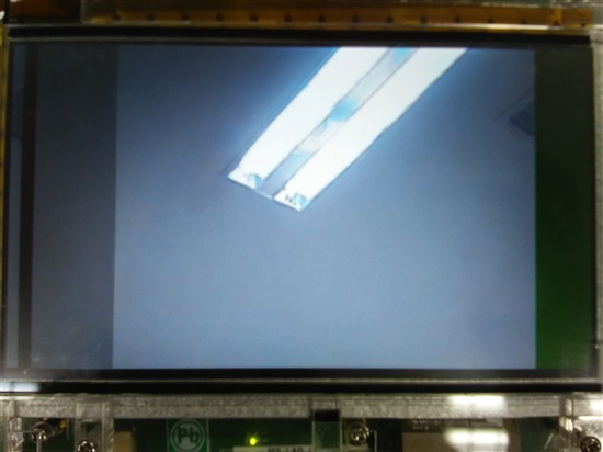
    After setting invertFidPol, the image is like that:

  • Hi,


    Yes, you could this field for inverting FID.. But this will be done on VIP, not in decoder.

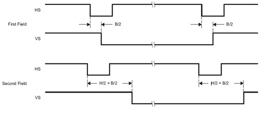
    From the description, it looks like your hsync is not positioned correctly in the decoder. As i said, VIP will capture even the horizontal blanking area in the hsync style of capture. VIP is really dumb in this case, it just captures whole line when hsync goes high. So if your hsync is not positioned correctly in the decoder, it could give different blanking area for each field. Could you please check the hsync start position for each field in the decoder registers?


    Regards,

    Brijesh

  • Hi

    TVP5147 has not register to set field sync offset.

     AVID and HSYNC related registers are 0x16-0x1D, they can't be used to control single field.

  • I took below paragraph from the TVP5147 specs

    VS, HS, and VBLK are independently software programmable to a 1× pixel count. This allows any possible
    alignment to the internal pixel count and line count. The default settings for 525-line and 625-line video outputs
    are given as examples below. FID changes at the same transient time when the trailing edge of vertical sync
    occurs. The polarity of FID is programmable by an I2C interface.


    So it is possible to program hsync start position.

    Could you also check the polarity of the hsync and vsync signals?

    Can you also read VIP registers 0x48105530 for each field and share it?

    Could you please also check if the buffer is 16byte aligned?


    Regards,

    Brijesh

  • Please go through the below link to know changed required on Catalog board for hte TVP5147 input.


    http://e2e.ti.com/support/dsp/davinci_digital_media_processors/f/717/p/326172/1170822.aspx#1170822


    Regards,

    Brijesh