This thread has been locked.

If you have a related question, please click the "Ask a related question" button in the top right corner. The newly created question will be automatically linked to this question.

LCD issue

Guru 20755 points

Hello,

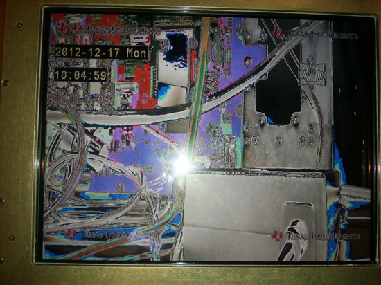
I have some issue with LCD monitor, when using RDK 4.1.0.2, 

I have verified that the color bars is OK, and it is excellent, but on moving to video, I get the following behavior.

With the EVM LCD, I had excellent results.

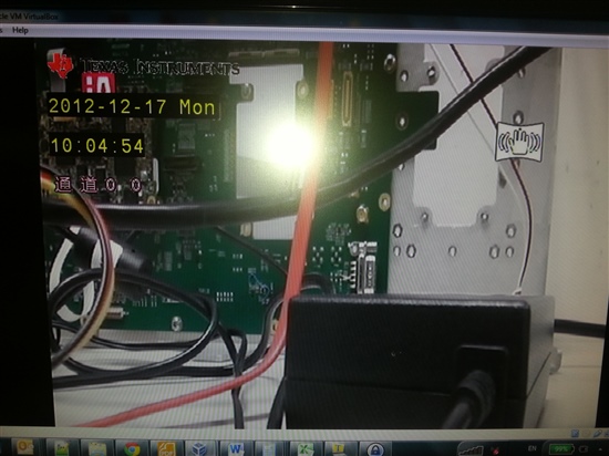
This is the correct video picture I need to see:

Thanks for any idea,

Ran

  • You mentioned the colorbar, is it the DM81xx's VENC's test pattern, or the LCD controller itself generated colorbar ?

  • Hi Eason,

    Thank you very much for the quick response.
    I am using DM81XX's VENC test pattern:

    echo 0 > /sys/devices/platform/vpss/graphics0/enabled
    echo 0 > /sys/devices/platform/vpss/display1/enabled
    echo 65000,1024/24/160/136,768/3/29/6,1 > /sys/devices/platform/vpss/display1/timings
    echo triplediscrete,rgb888 > /sys/devices/platform/vpss/display1/output
    echo 1 > /sys/devices/platform/vpss/display1/enabled
    cd /opt/dvr_rdk/ti814x/bin
    ./mem_rdwr.out --wr 0x4810a000 0x4403b011

    Regards,

    Ran


  • Hi I doubt it might be a mixed problem.

    Maybe you can measure the RGB signals directly , through MSB to LSB.   I guess there are bits missing 

  • Hi Eason,

    I validated the pinmux setting, and it is correct (all vout[0] pins are used):

    0x48140ab8: 00000001
    0x48140abc: 00000001
    0x48140ac0: 00000001
    0x48140ac4: 00000001
    0x48140ac8: 00000001
    0x48140acc: 00000001
    0x48140ad0: 00000001
    0x48140ad4: 00000001
    0x48140ad8: 00000001
    0x48140adc: 00000001
    0x48140ae0: 00000001
    0x48140ae4: 00000001
    0x48140ae8: 00000001
    0x48140aec: 00000001
    0x48140af0: 00000001
    0x48140af4: 00000001
    0x48140af8: 00000001
    0x48140afc: 00000001
    0x48140b00: 00000001
    0x48140b04: 00000001
    0x48140b08: 00000001
    0x48140b0c: 00000001
    0x48140b10: 00000001
    0x48140b14: 00000001
    0x48140b18: 00000001
    0x48140b1c: 00000001
    0x48140b20: 00000001
    0x48140b24: 00000001
    0x48140b28: 00000001

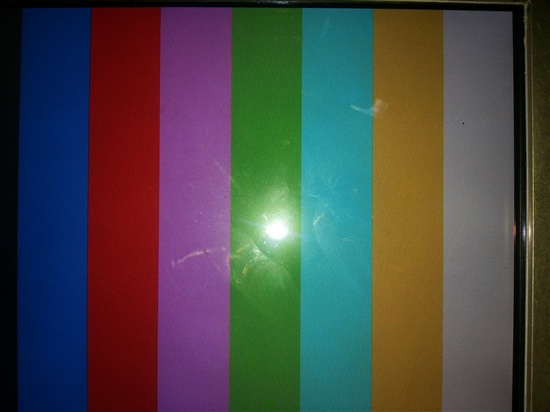
    This is the color bar I get:

    Is it that you suggest to see for each bit (using scope) the values ? Should I do it when the color bar is used or with the video ?
    What should I expect to see in each bit ?

    Is seems a bit that the black color is not complete black but a bit grey. Maybe this is indication for some missing bits ? The other color seems fine.

    Thanks,

    Ran

  • Hi ,

    It is very strange that colorbar is good but the real data is not.

    I just guess there is something wrong w/ your usecase, but it is too early to say.

    'Steps' are observed from you picture so I  guess some bits missing.

    Or maybe you can also feed colorbar or other test pattern in your usecase(not the venc's build-in colorbar), it can be more easier to recognize.

    I will also suggest you confirm that the build-in colorbar result is correct(you can compare w/ build in HDMI or SDDAC),   because  I dont remember what the exact sequence that these colors are, which color should come first and which is next.   

    BR,

    Eason

  • Since your connection is RGB, so when you enable the colorbar on RGB(DVO1), the build in HDMI should also gives colorbar.   

  • Hi Eason,

    Thanks very much for the ideas, I will check the issues you've suggested and get back to you.
    I suppose that we should expect to see repeating changes from 0<->1 in each of the 24bits pins while the color bar is presented. 

    I  also noticed that in EVM LCD the black (from the color bar) is complete black, while in the custom LCD it is grey (though I am not yet sure if it is an issue of brightness or lost bits).

    Regards,

    Ran

  • You mention that the EVM is OK. Is this issue on your own hardware platform?

    I am concerned that in the 'real' images the black regions are not black, but white.

    Can you please post your schematics for the DVO portion.

    Can you send the LCD datasheet?

    What is the orientation of the LCD panel? The white bar should be on the left.

    What is the interface between the DM and the LCD? Direct connect through parallel CMOS, LVDS, HDMI etc...?

    BR,

    Steve

  • Hi Steve , Eason

    Thanks a lot for the support. I am not at the lab now, but I have answers few of the questions.

    >I am concerned that in the 'real' images the black regions are not black, but white.

    I'm not sure what you mean. The issue I noticed with the color bar in the custom LCD, is that although it looks very well, the black column (the most right column, looks like grey ,though I am still not sure if only because of  brightness it looks like that), in EVM LCD it looks totally black.

    >Can you please post your schematics for the DVO portion.
    >Can you send the LCD datasheet?

    I will attach both by Sunday morning 

    >What is the orientation of the LCD panel? The white bar should be on the left.

    Yes, the white is on the left (in my previous post the colorbar image is rotated)

    >What is the interface between the DM and the LCD? Direct connect through parallel CMOS, LVDS, HDMI etc...?

    LVDS (I will send later the block diagram)

    Thank you very much,

    Ran

  • Ahhh.... LVDS !!!!


    There are 2 different formats for LVDS connectivity which will swap color bits. Make sure your connectivity to the LVDS transmitter is implemented to match what the LCD panel requires.

    Please see the following link for a full explanation of LVDS connectivity.
    http://processors.wiki.ti.com/index.php/LCD_connectivity#Connection_to_LVDS_LCDs

    By "black regions are not black" I mean if you look at the power supply brick in the video image you show the black plastic is not black, but is white/gray"

    BR,

    Steve

  • Hi Steve,

    Thanks, we will check this as soon as possible.  But I wander, if there is "swap color bits" because of LVDS, shouldn't we expect the colorbar to be color-distorted too ?

    Thanks,

    Ran

  • No since the color bar turns each or red, green and blue color completely on or off. The LVDS switching moves the color bits around within the color groups of bits, i.e. green MSB becomes green LSB etc...

    If the color bar displayed colors which were not pure colors then you would see the issue.

    BR,

    Steve

  • Hi Steve, Eason

    We made some checking on HW & SW :
    Our LCD is 18 bits, and we connected the LSB bits, while in the wiki we see that the MSB bits should be connected, so we suspect it is a matter of wrong connection.
    We also configure by HW the LCD to work with pulse down. Do you think it is OK , ot should it be by pusle up ?
    What about the HDVPSS configuration for display. There are several configuration registers used. Do I need to make any changes in it ?

    We also consider now to configure the chip to work with 18 bits LCD, instead of making HW changes. Do you think this is possible ?

    Thank you for your time,

    Ran

  • Hi,


    If You are using sysfs for configuring your LCD, then there is no need to change VENC registers manually, driver will configure the VENC correctly.

    Please also note that the VENC will output 24bit RGB data, to make it work with 18bit LCD, you will need to drop 2 LSBs in each color component. Before this, can you please check if you are outputting RGB data?


    Regards,

    Brijesh

  • Depending on which VENC you are using it might be possible to use the gamma correction or CSC to effectively shift the upper 6 bits down to the lower bits, but this would be completely unsupported and you would need to calculate the settings yourself (basically a linear transfer with factor 0.25).

    The best solution though is to correctly utilize the upper 6 bits. Another advantage of this is that if you ever switch to a 24 bit LCD it should be simpler to update.

    BR,

    Steve

  • Hi All,

    With the new HW fix (6 MSB bits instead of the LSB bits), it works perfect.
    Thank you all very very much !!!

    regards,

    Ran

  • Excellent. Glad you are working correctly now.

    BR,

    Steve

  • Ran,

    I guess you mean MSB instead of LSB and not LSB instead of MSB?

    Just a clarification in case anyone else views this posting.

    MSB from source should always go to MSB of the sink for each color channel.

    BR,

    Steve

  • Right, I've fixed my previous post.

    Thanks!

  • Hello Steve,

    I would like to ask one more on this issue please , and hear your advise, if possible.

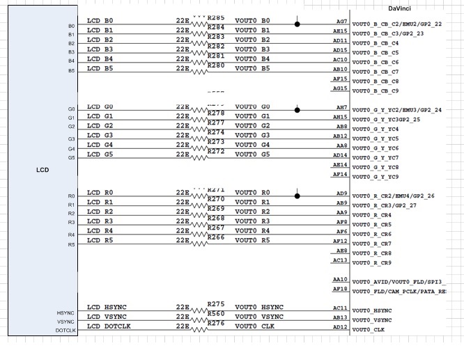
    We had similar (but different) project in which we had the same wrong connectivity done (though it does not use LVDS but LCD), but we already have several products, so we some dilemma if we should: 1. change the tailoring in all the boards 2. use the gamma correction which you mentioned before.

    Can you please review the below schema (it does not use LVDS here but LCD), and advise if we can use the gamma correction , or better do the fixing in HW ?
    If gamma correction is advisable here - how should it be done ?

    Thank you,

    Ran

     Hello Steve,