This thread has been locked.

If you have a related question, please click the "Ask a related question" button in the top right corner. The newly created question will be automatically linked to this question.

Blinking Led Example Project LCDK OMAP-L138 doesn't work

Other Parts Discussed in Thread: OMAP-L138, OMAPL138

Hey everyone,

I got myself LCDK OMAP-L138 and XDS100V2 debugger.

I try to run the blinking led project on the ARM processor but I can't seem to make the LEDs blink.

I guess I don't understand the multiplexing process but even when I use the sample as is, it doesn't work.

I tried altering the program to use the user buttons as triggers.

The buttons do trigger but the LEDs still don' turn off.

Here is my code:

int main(void)
{
    /* The Local PSC number for GPIO is 3. GPIO belongs to PSC1 module.*/
    PSCModuleControl(SOC_PSC_1_REGS, HW_PSC_GPIO, PSC_POWERDOMAIN_ALWAYS_ON,
         PSC_MDCTL_NEXT_ENABLE);

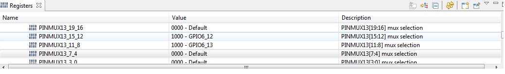
    /* Pin Multiplexing of pin 12 of GPIO Bank 6.*/
    GPIOBank6Pin12PinMuxSetup();

    /* Sets the pin 109 (GP6[12]) as input.*/
    GPIODirModeSet(SOC_GPIO_0_REGS, 109, GPIO_DIR_OUTPUT);
    /* Sets the pin 110 (GP6[13]) as input.*/
    GPIODirModeSet(SOC_GPIO_0_REGS, 110, GPIO_DIR_OUTPUT);

    GPIODirModeSet(SOC_GPIO_0_REGS, 37, GPIO_DIR_INPUT);
    GPIODirModeSet(SOC_GPIO_0_REGS, 38, GPIO_DIR_INPUT);

    while(1)
    {
         if(GPIOPinRead(SOC_GPIO_0_REGS, 37) == GPIO_PIN_LOW)
         {
             GPIOPinWrite(SOC_GPIO_0_REGS, 109, GPIO_PIN_HIGH);
             GPIOPinWrite(SOC_GPIO_0_REGS, 110, GPIO_PIN_HIGH);
         }
         if(GPIOPinRead(SOC_GPIO_0_REGS, 38) == GPIO_PIN_LOW)
         {
             GPIOPinWrite(SOC_GPIO_0_REGS, 109, GPIO_PIN_LOW);
             GPIOPinWrite(SOC_GPIO_0_REGS, 110, GPIO_PIN_LOW);
         }
     }
}

Help, anyone?

Thanks,

Joel

  • One problem is that you haven't set up the pinmux for pin 110.  You need to add a function like GPIOBank6Pin13PinMuxSetup()

    void GPIOBank6Pin13PinMuxSetup(void)
    {
    unsigned int savePinmux = 0;

    /*
    ** Clearing the bit in context and retaining the other bit values 
    ** in PINMUX13 register.
    */
    savePinmux = (HWREG(SOC_SYSCFG_0_REGS + SYSCFG0_PINMUX(13)) &
    ~(SYSCFG_PINMUX13_PINMUX13_11_8));

    /* Setting the pins corresponding to GP6[13] in PINMUX13 register.*/
    HWREG(SOC_SYSCFG_0_REGS + SYSCFG0_PINMUX(13)) =
    (PINMUX13_GPIO6_13_ENABLE | savePinmux);

    }

    Also, you have to be in privileged mode to change the pinmux registers.

    I was able to get all the LEDs to work on the LCDK by adding GPIO LED support to the starterware bootloader and using that to load my ARM application.

  • Hey Aaron,

    Thanks for the help.

    The problem was the .cmd file that was automaticly used when I changed the device int the project properties, when I changed it back, it worked.

    You are right about the muxing part for the other LED.

    Joel

  • Hi


    Where is this macro defined:

    PINMUX13_GPIO6_13_ENABLE

    Where I can similar definition for GPIO2[4]

    if can not be found anywhere how to define it.


    Thanks

  • Attached are the files I modified from the root OMAPL138_StarterWare_1_10_03_03 directory.  I was running the echoApp demo.

    Best regards,

    Aaron

    4300.lcdk_led_echoApp_changes_SW1_10_03_03.zip

  • Hi Aaron


    which libraries are used to link the following symbols:


    PSCModuleControl

    GPIOBank6Pin12PinMuxSetup   

    GPIODirModeSet

    GPIOPinRead

    GPIOPinWrite


    Thanks


  • Hey Hatem,

    From the OMAPL138_StarterWare_1_10_03_03 directory you can find "psc.h" and "gpio.h".

    Furthermore, to config the pin multiplexing, you can use a small app called: "PinMux" (surprise surprise) 0576.PinMux.zip

    and then just change the wanted pinmux registers with the received values, like that:

    /* The Local PSC number for GPIO is 3. GPIO belongs to PSC1 module.*/
    PSCModuleControl(SOC_PSC_1_REGS, HW_PSC_GPIO, PSC_POWERDOMAIN_ALWAYS_ON,
    PSC_MDCTL_NEXT_ENABLE);

    // Select GP8[10] (139) and GP8[12] (141) as GPIO's
    HWREG(SOC_SYSCFG_0_REGS + SYSCFG0_PINMUX(18)) |= 0x80800000;

    Best regards,

    Yoel

  • Hello,

    Getting an error "expression must be an modifiable lvalue" at following statement

    HWREG(SOC_SYSCFG_0_REGS + SYSCFG0_PINMUX(13)) =  0x00000088;

    Thank you in anticipation

    Best Regards

    Kalyani

  • Please make sure that you have included the "hw_types.h" file.
  • Thank you Titus.

    Yes you are right. After including "hw_types.h" file the error is resolved but now getting one more error as "unresolved symbol SYSCFG0_PINMUX, first referenced in ./gpioCardDetect.obj". I have imported gpio example from starterware and trying to modify the same code. 

    Thanks in advance

    Regards

    Kalyani

  • Also you need to include the #include "hw_syscfg0_OMAPL138.h" this file as well.
  • Similarly after adding "hw_syscfg0_C6748.h" above error is solved. But only one LED is blining. My aim is to blink two LEDs.

    Now my program is as follows:


    #include "gpio.h"
    #include "psc.h"
    #include "soc_C6748.h"
    #include "lcdkC6748.h"
    #include "hw_types.h"
    #include "hw_syscfg0_C6748.h"

    /****************************************************************************/
    /* LOCAL FUNCTION PROTOTYPES */
    /****************************************************************************/
    static void Delay(volatile unsigned int delay);

    /****************************************************************************/
    /* GLOBAL VARIABLES */
    /****************************************************************************/

    /****************************************************************************/
    /* LOCAL FUNCTION DEFINITIONS */
    /****************************************************************************/
    void GPIOBank6Pin13PinMuxSetup(void);

    int main(void)
    {
    /* The Local PSC number for GPIO is 3. GPIO belongs to PSC1 module.*/
    PSCModuleControl(SOC_PSC_1_REGS, HW_PSC_GPIO, PSC_POWERDOMAIN_ALWAYS_ON,PSC_MDCTL_NEXT_ENABLE);

    GPIOBank6Pin12PinMuxSetup();
    GPIOBank6Pin13PinMuxSetup(); // kalyani
    GPIODirModeSet(SOC_GPIO_0_REGS, 109, GPIO_DIR_OUTPUT);
    GPIODirModeSet(SOC_GPIO_0_REGS, 110, GPIO_DIR_OUTPUT); //kalyani
    while(1)
    {
    GPIOPinWrite(SOC_GPIO_0_REGS, 109, GPIO_PIN_LOW);
    GPIOPinWrite(SOC_GPIO_0_REGS, 110, GPIO_PIN_LOW); //kalyani
    Delay(1000000);
    GPIOPinWrite(SOC_GPIO_0_REGS, 109, GPIO_PIN_HIGH);
    GPIOPinWrite(SOC_GPIO_0_REGS, 110, GPIO_PIN_HIGH); //kalyani
    Delay(1000000);
    }

    }

    static void Delay(volatile unsigned int delay)
    {
    while(delay--);
    }


    void GPIOBank6Pin13PinMuxSetup(void)
    {
    HWREG(SOC_SYSCFG_0_REGS + SYSCFG0_PINMUX(13)) = 0x00008800;
    }

    Please help me.

    Thank you
    Regards
    Kalyani
  • Thank you very much,
    Error is solved now. But only one LED is blinking whereas my aim is to blink two LEDs.
    Program is as follows:
    #include "gpio.h"
    #include "psc.h"
    #include "soc_C6748.h"
    #include "lcdkC6748.h"
    #include "hw_types.h"
    #include "hw_syscfg0_C6748.h"

    /****************************************************************************/
    /* LOCAL FUNCTION PROTOTYPES */
    /****************************************************************************/
    static void Delay(volatile unsigned int delay);

    /****************************************************************************/
    /* GLOBAL VARIABLES */
    /****************************************************************************/

    /****************************************************************************/
    /* LOCAL FUNCTION DEFINITIONS */
    /****************************************************************************/
    void GPIOBank6Pin13PinMuxSetup(void);

    int main(void)
    {
    /* The Local PSC number for GPIO is 3. GPIO belongs to PSC1 module.*/
    PSCModuleControl(SOC_PSC_1_REGS, HW_PSC_GPIO, PSC_POWERDOMAIN_ALWAYS_ON,PSC_MDCTL_NEXT_ENABLE);

    GPIOBank6Pin12PinMuxSetup();
    GPIOBank6Pin13PinMuxSetup(); // kalyani
    GPIODirModeSet(SOC_GPIO_0_REGS, 109, GPIO_DIR_OUTPUT);
    GPIODirModeSet(SOC_GPIO_0_REGS, 110, GPIO_DIR_OUTPUT); //kalyani
    while(1)
    {
    GPIOPinWrite(SOC_GPIO_0_REGS, 109, GPIO_PIN_LOW);
    GPIOPinWrite(SOC_GPIO_0_REGS, 110, GPIO_PIN_LOW); //kalyani
    Delay(1000000);
    GPIOPinWrite(SOC_GPIO_0_REGS, 109, GPIO_PIN_HIGH);
    GPIOPinWrite(SOC_GPIO_0_REGS, 110, GPIO_PIN_HIGH); //kalyani
    Delay(1000000);
    }

    }

    static void Delay(volatile unsigned int delay)
    {
    while(delay--);
    }


    void GPIOBank6Pin13PinMuxSetup(void)
    {
    HWREG(SOC_SYSCFG_0_REGS + SYSCFG0_PINMUX(13)) = 0x00008800;
    }

    Only GP6[12] LED is blinking.


    Thanks in advance.
    Regards
    Kalyani
  • Please make sure that you have done pinmux correctly for that GPIO which is not blinking.
    You can check the value of PINMUX register using CCS register window.
  • Thank you Titus,

    I have checked the value of PINMUX register using CCS window. Both GPIOs are enabled. Here is the snapshot.

    Regards

    Kalyani

  • Please check the corresponding GPIO SET and CLEAR register while non-working GPIO toggling time.
    Please make sure that your LED is in working condition, you can also probe the correct LED.

    Refer to the following post where I have given some LED and DIP switch example.
    e2e.ti.com/.../1306278
  • Dear Titus,

    I have modified the program just to "ON" the LED's. As you see in the above fig. In the registers section GP6P12 AND GP6P13  OUT VALUE is SET TO 1, but on the board led is not "ON".

    Thanks

    Kalyani

  • Have you tried the example which I given in the last post ?
  • Yes,

    Program is executed properly but it is also not working on board. 

    Thanks  

    Kalyani 

  • Have you changed the DIP switch on LCDK board to blink the LEDs ?
    If still its not working, better to probe at LED pins and make sure that LED is in good condition.

    That code was tested on both C6748 and OMAPL138 LCDK boards.
  • Hi,


    I am trying to make a small program  to blink a led using an OMAP l-138 LCDK board that is running linux kernel 3.3.0.

    Could you please me explain me how can i make such a program?


    Thanks,