This thread has been locked.

If you have a related question, please click the "Ask a related question" button in the top right corner. The newly created question will be automatically linked to this question.

TCA9546A Communication

Other Parts Discussed in Thread: TCA9546A

Hi.
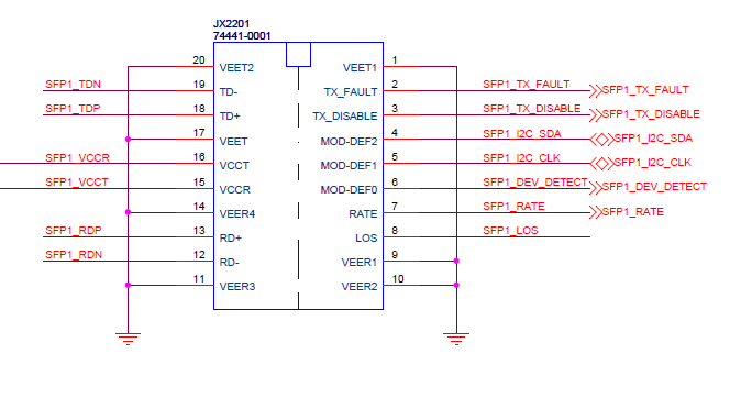
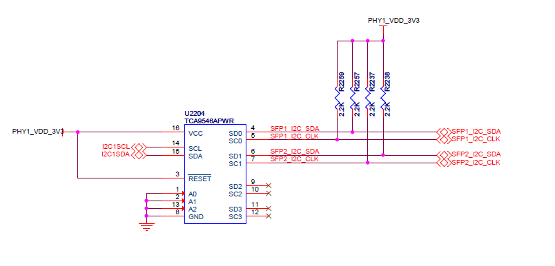
We have a DM8148 custom board  with TCA9546A on i2c2 (count from 1) bus. To the TCA9546A i2c switch we have connected two cages that are connected to a phy (see drawing attached). 
I don't really manage to understand how to communicate with the endpoints.

We currently testing with a SFP-1GBT-05 adapter in the cage, and the datasheet of the adapter mentions i2c address ACh and EEPROM address A0h.

I have tried using the following command to make the communication go through channel SD1 in the TCA9564A chip:

i2cset -f -y 2 0x70 0x1

I know i am definitely talking with the correct device as this is the only device on the bus and it's address it 0x70 (checked in the datasheet).

But when i do:

i2cget -f -y 0x70 0xAC

or

i2cget -f -y 2 0x70 0xA0

i get 0x0C and 0x00 respectively, which is the data address with the first nibble masked.

Can you help me please with the correct command used to read the data (device_id) of the adapter connected to the cage?


Kind Regards

  • Hello Moon,

    Thanks for the question.

    I think I do not understand what your issue is.

    Please help me by acknowledging if my assumptions are true or not:

    1) You send 0x01 to the TCA9536A, and it seems to properly connect channel 0 (SC0/SD0) to the main I2C1 lines.

    2) The address of your TCA9546A is 0x70. What is the address of the device you are attempting to communicate with on the SD0/SC0 lines? Is it 0x70?

    It seems like from your command, that you are trying to communicate with another device on your I2C bus with the same address as your I2C switch. You cannot have 2 devices with the same I2C address on your bus!

    You will have to change the address of your switch by pulling one of the address pins high. I would suggest just pulling up A0 to VCC, then your switch address would be 0x71.
  • Hi. 
    Thanks for prompt reply. Sorry i got confused in the command i wrote to you. I did manage to communicate with SD0/SC0 lines using the command:

    i2cset -y -r 2 0x70 0x1

    When i do that, i can see new device on address 0x50 in the chip. When i read the address i can see the contents of the EEPROM of the PHY transceiver.
    According to the transceiver datasheet, the eeprom is on i2c address A0 (which in 7-bit addressing becomes 0x50 if i understand correctly). The datasheet says the PHY registers address is 0xAC (which in 7-bit addressing becomes 0x56), but i can see nothing on this address. Actually when i scan the bus i see only addresses 0x70 and 0x50.

    Is there something i am missing. Why aren't all the addresses of the device showing up??

    Thanks for you help :)

  • Hello Moon,

    I think you're getting confused between address of the device and a register address.

    The address of the device is a 7 bit address (0x50 is the correct interpretation). The address of a register is always 8 bits, and comes AFTER the device address to tell the device which internal register you want to read or write from. This means that you should not take the 0xAC register and make it 7 bits.

    I would suggest looking at this appnote: www.ti.com/.../slva704.pdf
    Sections 3 to 3.2 should help illustrate this.

    So you are actually seeing the device (0x50) once you configure the switch. You should not modify the register address(IE write 0xAC after your 0x50 address + R/W bit part).
  • Hi Jonathan.

    I do understand the difference between device address and register address. The PHY address is as mentioned 0xAC, and the EEPROM address is 0xA0 (which shifted left becomes 0x56 and 0x50 respectivly). and I do actually see the EEPROM at address 0x50 on the bus (when i use i2cdump on that address on the bus i see the EEPROM contents). my question is why can't i see the addres 0x56 on the bus. This address should contain some phy registers (which i am interested in reading/setting). My problem is that i can't see anything (no device) on the PHY address but can see the EEPROM address. 
    The device PHY transciever and for that reason should be automatically detected, both PHY and EEPROM. but only EEPROM is showing up.

    Is my problem more clear now?

    for example if i would like to read AN_RX (auto-negotiation receive) register of the PHY, to see auto-negotiation values, i must write to bus number 2, phy address 0xAC (according to data sheet), register address 0x5, value bla bla. But i can see only EEPROM address 0x50 (0xA0 >> 1), but no phy address 0x56 (0xAC >> 1).

  • Moon,

    My mistake, I misinterpreted your previous post. I now understand. 

    I'm not sure why the device is not showing up, but if they are all connected to the same switch channel, then you should have access to it. What I have seen in the past, is that some devices will not ACK until you send a write request. I know several of our TI devices behave this way if you power them up, and if you only send their address with a read request, they will NACK until you first send a write request with an internal address.

    I'm not sure which PHY you're using, but you may be seeing this same behavior.

    Also, lets verify your setup in your schematic. 

    Phy is connected to Channel 0?

    EEPROM is connected to channel 0 as well?

    We know the switch is working since you can connect/transfer data with the EEPROM.

  • Hi.
    The fake write to the address has solved it. 
    Thank you very much

  • Moon,

    Glad to hear it!

    As an FYI, the 'fake write' you are referring to is designed to let the slave device know which register you want to read. Upon a fresh power up, the slave does not know which register to read from when you send a read request, so it NACKs.

    When you send a write command and supply the register address, you then do a repeated start and send a read request. The slave will read back from the register address you supplied in your write command.

    Please see figure 9 on page 7 in the I2C App note: www.ti.com/.../slva704.pdf

  • Hi Moon,

    I also have a similar problem I have SFP which has PHY in it (0xAC). It is behind a MUX I was able to do a EEPROM access which is 0x50. But could not fine any device 0x56( 0xAC -PHY). What is the "fake write to the address"you have done ? Could you show some light on below

    ------------------
    # i2cset -f -y 4 0x56 0x0
    Error: Write failed

    -----------------------
    # i2cdetect -y 4
    0 1 2 3 4 5 6 7 8 9 a b c d e f
    00: -- -- -- -- -- -- -- -- -- -- -- -- --
    10: -- -- -- -- -- -- -- -- -- -- -- -- -- -- -- --
    20: -- -- -- -- -- -- -- -- -- -- -- -- -- -- -- --
    30: 30 -- -- -- -- -- -- -- -- -- -- -- -- -- -- --
    40: -- -- -- -- -- -- -- -- -- -- -- -- -- -- -- --
    50: 50 -- -- -- -- -- -- -- -- -- -- -- -- -- -- -- >>>>>>>>>>>>> only 50 could be seen here EEPROM
    60: -- -- -- -- -- -- -- -- -- -- -- -- -- -- -- --
    ------------------------------------

    Whats should I write to 0x56 ? to see is visible ?
  • Hi Moon,

    I do have similar issue and followed your instructions of doing a dummy write at 0x56 but the standard linux tool reports error and could not see 0x56 (0XAC) phy by any means. Could you let me know what is the exact dummy write we need to do.

    --------------

    # i2cset -f -y 4 0x56 0x0
    Error: Write failed

    # i2cdetect -y 4
    0 1 2 3 4 5 6 7 8 9 a b c d e f
    00: -- -- -- -- -- -- -- -- -- -- -- -- --
    10: -- -- -- -- -- -- -- -- -- -- -- -- -- -- -- --
    20: -- -- -- -- -- -- -- -- -- -- -- -- -- -- -- --
    30: -- -- -- -- -- -- -- -- -- -- -- -- -- -- -- --
    40: -- -- -- -- -- -- -- -- -- -- -- -- -- -- -- --
    50: 50 -- -- -- -- -- -- -- -- -- -- -- -- -- -- -->>>>>>>>>>>>>>> we could only see 0x50.
    60: -- -- -- -- -- -- -- -- -- -- -- -- -- -- -- --
    70: UU -- -- -- -- -- -- --
    # i2cset -f -y 4 0x56 0x0
    Error: Write failed
    Thanks
    Sri
  • Hello Sri,

    In your case, ti sounds like there is a device communication issue. Can you get screen shots on a scope at the IC and verify what's going on?

    If the IC is not responding to a read or a write request, it appears there is something else happening.
  • Hi Sri.

    I think you are confusing the two ICs, The fake write was to the TCA9546 at address 0x70. It seems that you configured your TCA9546 correctly if you can see EEPROM contents at address 0x50. I've had a similar issue with one of the SFP connectors, but it was a specific one which did not show up at address 0x56 (just like yours). The rest were showing up at 0x56 and 0x50.

    So it seems to me that your SFP connector have not initlalizaed it's phy component correctly.

    Good luck.

  • Hi MoonDrop,

    Thanks for your quick answer. So can you suspect that the problem could be with SFP Physical Device ?? when you say "SFP connector have not initlalizaed it's phy component correctly" what do you mean by that.

    Yes, I am able to see EEPROM at 0x50 but not 0x56 :(. What would you suggest ,ways to debug.
    Thanks
    Sri
  • Hi Sri.

    Your connector is an IC made out of few components. one of them is the EEPROM which has i2c access on chip address 0x50 (which you see), one of them is the PHY which also has i2c access but on address 0x56 (usually so, if you follow standards). It seems that you can see only the EEPROM IC component, but not the PHY IC component. For debugging i would suggest to first try another converter (another company), I would also try and see the manufacturer's EEPROM contents, maybe there is kind of error status register. 
    Also there are additional (some optional) lines going to the SFP connectors - tx_fault, tx_disable, dev_detect, rate (optional). 
    TX_DISABLE is output from the processor, make sure this line is tied low when you activate the PHY. After a successful PHY initialization, the PHY will de-assert tx_fault line which should indicate that it is ready to transmit. Reset your PHY and check that this line has been tied low shortly after reset.
    Last thing you can try is to change the sequence of initializations of the components (in my case when configuring the tx_fault, tx_disable, dev_detect and rate gpios BEFORE asserting ETH_RST would cause the phy not to start, changing the sequence of those made it work for me, i.e first assert ETH_RST, then initialize tx_fault, tx_disable, dev_detect and rate as GPIO and give values).

    Hope that helps :)