This thread has been locked.

If you have a related question, please click the "Ask a related question" button in the top right corner. The newly created question will be automatically linked to this question.

DS90UB953 to DS90UB954 synchronized interleave output working but not at high speed

Part Number: DS90UB954-Q1
Other Parts Discussed in Thread: DS90UB960-Q1,

Hello friends,

I've have the following system working..

4k60 test pattern generator split into even & odd lines and converted to two CSI-2 streams.  Streams are input to DS90UB953 serializers and sent (over coax) to attached DS90UB954 deserializer.  954 can output correct rebuilt test pattern frames as CSI-2 from the received interleaved data if I run the system at 36 fps.  If I run it at speed (60fps) the output of the 954 lines are corrupted and the actual output line count is short.  (see images below for better understanding, please)  I need best thoughts on what may be happening here.  I don't think this is just a simple signal integrity issue.  I looks more like a fifo overflow issue by how the lines are broken off at the same point in each data set.  This could be due to the 954 not successfully seeing line ends or frame ends, but I don't really know.  Looking for ideas.

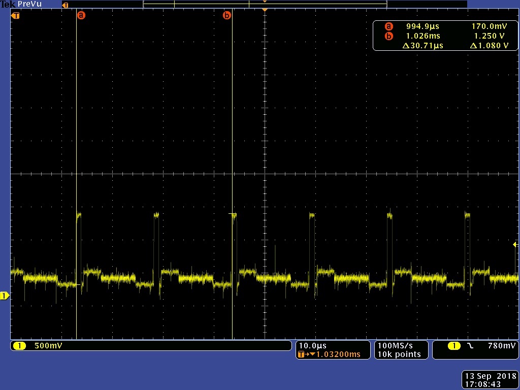
Input to channel #1 953:

The input to the 1st 953.  (0xff, oxff, 0xaa, 0xaa, 0xaa, 0xaa, 0x00, 0x00) (each of the preceding numbers is actually 600 bytes or 480 10bit words for a total line length of 3840 pixels)

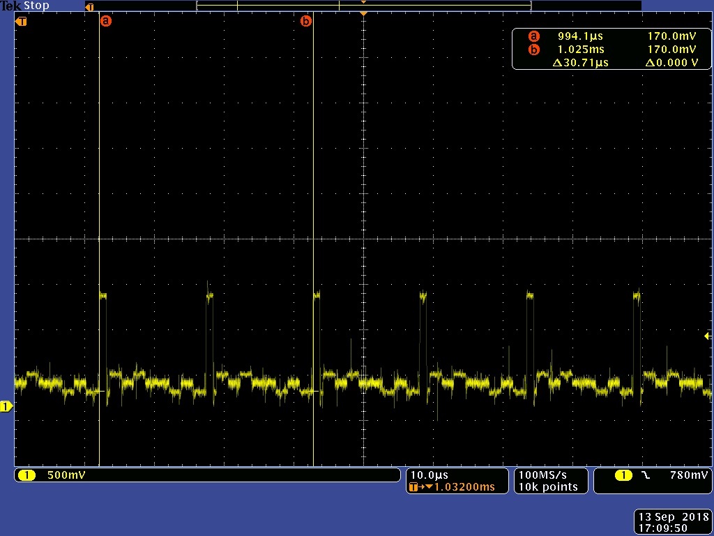
Input to channel #2

The input to the 2nd 953.  (0xff, 0xaa, 0xff, 0xaa, 0xaa, 0x00, 0xaa, 0x00) (each of the preceding numbers is actually 600 bytes or 480 10bit words for a total line length of 3840 pixels)

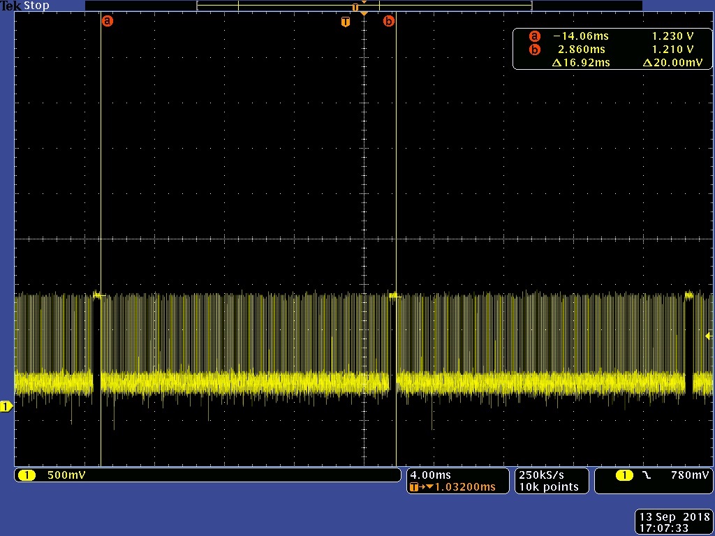
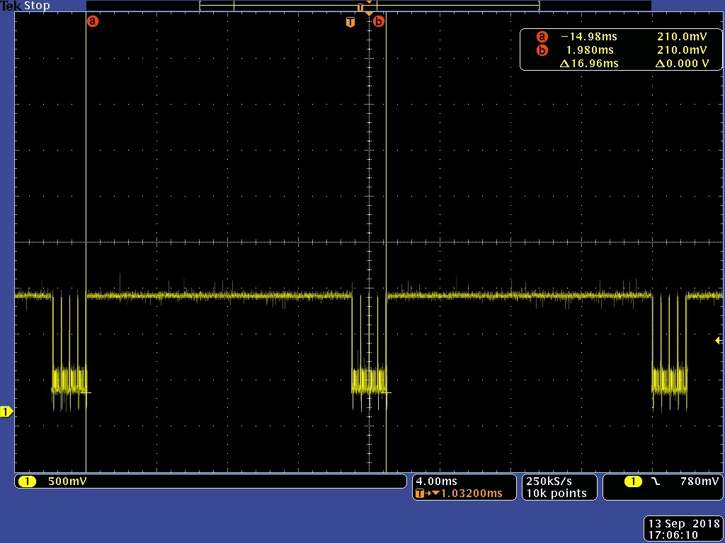
953 input frame rate:

You can see that the input frame rate to the 953's is roughly 16.92ms or 59.1Hz. 

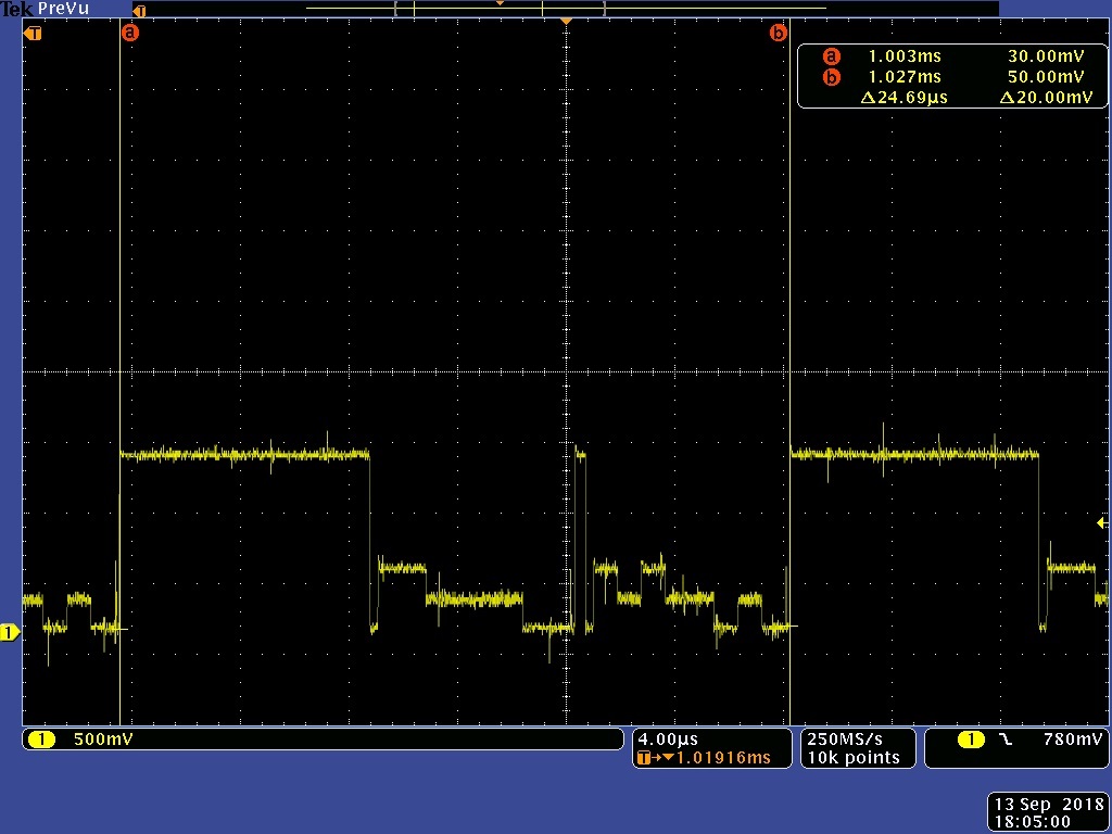
954 CSI-2 output:

These are the recombined interleaved lines from the 954 CSI-2 output.  You can see the the beginning of each line is correct but the back half of the line data is not present...  the total time for each line looks correct (if you measure between two counts of the LP11 portions of the stream) as two input lines to the 953 took 37.91usecs and two lines out of the 954 takes about half that amount.  This is to be expected since we had two CSI-2 streams at the 953's and only one at the 954 --> should be twice as fast. 

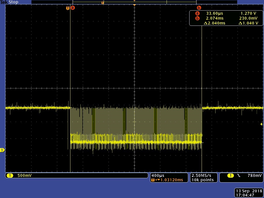
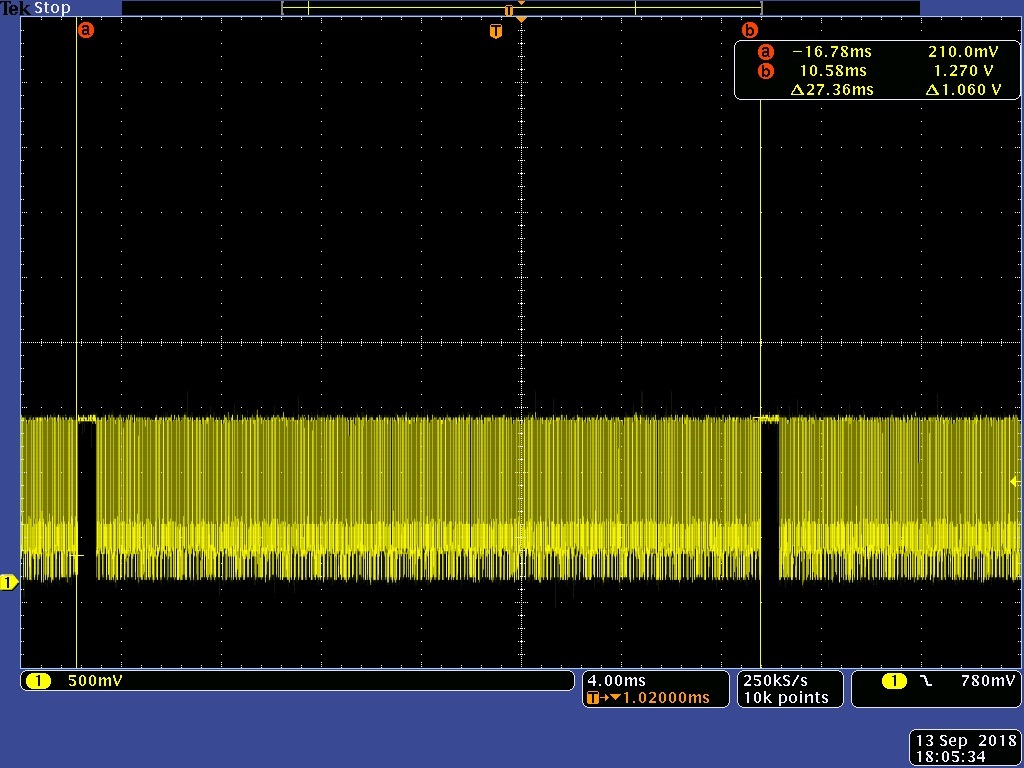
954 CSI-2 output per frame:

These are the lines in any given single frame.  From the previous image it can be seen that the actual line lengths are correct but from this image you can see that the total line count per frame is only taking 2.04msec but should be taking 16.92msec.  Lines (albeit incorrect data) are moving at the correct rate but the count is short.

954 frame rate:

Note that the actual time between frame starts is correct (roughly 16.96msec) but the data (line count) has been truncated.  Remember that 16.96ms or 58.96Hz which is about the same as what we measured at the input to the 953's.  So the frame rate is correct.

954 CSI-2 output when running 37fps:

If I run the system from a slower refclk from channel #1 953 where I get only 36fps I get a waveform that is correct out of the 954 as shown below.  If you go back to the very top two images you will see that the recombined interleaved data below is correct. 

line #1 = (0xff, oxff, 0xaa, 0xaa, 0xaa, 0xaa, 0x00, 0x00) (each of the preceding numbers is actually 600 bytes or 480 10bit words for a total line length of 3840 pixels)

line #2 = (0xff, 0xaa, 0xff, 0xaa, 0xaa, 0x00, 0xaa, 0x00) (each of the preceding numbers is actually 600 bytes or 480 10bit words for a total line length of 3840 pixels)

954 CSI-2 output frame rate when running 36fps:

thanks,

david

  • I have been doing a little more investigation this morning and actually I can run the system successfully at 54fps not just 36fps. I still think that I have a setting incorrect somewhere rather than a signal integrity issue. The scope signals look good and the failure data is too consistent to just be noise. It looks more like I'm overflowing or under running a data buffer somewhere inside the 954.


    On the next thought.. I am using a 26Mhz oscillator at the 954 and running Synchronous from the REFCLK recovered at the 953.
    I am looking at the following numbers in the 953 documentation on page 18... I see the following:
    FC DATA RATE = f x 160 = 4.16Gbps
    CSI BANDWIDTH = f x 128 = 3.328Gbps
    These two numbers have the same units and I know what units Data Rate would have so I take the difference between the two (4.16 - 3.328Gbps = 832Mbps) to be the overhead taken up by the CSI-2 & FPDLink protocols or possibly just the FPDLink protocol. If the second idea is correct then the CSI-2 overhead is actually included in the 3.328Gbps number and that would mean the bandwidth for the actual CSI-2 data is even less... So, please help me understand exactly what bandwidth is available for actual data bits for an incoming CSI-2 stream when using a 26Mhz clk. I am outputting a 72Mhz clk.

    thanks,
    david
  • A little more information....

    Like I said before I have a 26Mhz clk at the 954 and am trying to use the equation "CLK_OUT = FC x (M/(HS_CLK_DIV x N)) to get my 953 clk output to drive the sensor system and CSI-2 data rate. I have the following parameters in the registers:
    953 reg 0x06 = 0x46
    953 reg 0x07 = 0x4E

    FC = 26Mhz x 160 = 4.16Gig
    HS_CLK_DIV = 0b010 = Div by 4
    M = 0x06 = 6
    N = 0x4E = 78

    These values should give me an output clock of (4.16G x (6/(4 x 78))) = 80Mhz.

    ...but... my scope measured clock is 65.06Mhz.

    I backtracked this frequency to the f value in (FC = 160 x f) and it looks like 21.144Mhz not 26Mhz.  Any thoughts on this?

    david

  • I've squeaked a little more speed out of it but not much... I'm just short of 58fps... Also, I am wanting to run at CSI-2 1.664 GHz and the documentation says that I need to overwrite the Indirect address registers having to do with the CSI TX port 0 Timing. Indirect addresses 0x40 - 0x48. Do you guys have a suggested set of values for these registers when running at 1.644 GHz.

    One other thing that I just noticed...  My CSI-2 output clock is 677.500Mhz giving a data rate of 1.355 Gbps/lane.  I have a 26Mhz REFCLK Frequency and the CSI_PLL_CTL register is set to 0x00.  The CSI-2 clock should be 800 or better since my input oscillator is 26Mhz. Why is this CSI-2 output clock so low?  I believe this is the problem.  I'm not moving data out fast enough when I start pushing the fps up....  Any ideas why the CSI-2 clock is not running at 1600Mbps?


    Sure would be nice if somebody would start answering a few of these posts.

    david

  • Hi David,

    Based on your description, it seems like the CSI-2 bandwidth exceeds the allowed maximum. Is it possible to run at 54fps? 

    You could calculate your CSI bandwidth using the following equation:

    • Bandwidth = Total Horizontal Samples (including blanking) * Total Vertical Lines (including blanking) * frame rate * # bits per frame * # cameras

    Then you can calculate the maximum CSI-2 bandwidth for the 954 CSI-2 port from page 42 of the DS90UB960-Q1 Datasheet (The 960 is the same as the 954 with 4 RX ports) and see if your bandwidth exceeds the maximum allowable bandwidth.

    Best,

    Jiashow

  • Hi Jiashow,

    I will look closely at the equations on page 42.

    In the meantime do you have any thoughts on why my output CSI-2 clock is too slow to support a data rate of 1.664Gbps?  My understanding is that the high speed clock is set simply by the chosen RefClk value and the CSI_PLL_CTL register value.  Is this correct or do I have a misunderstanding?

    Also, does TI have suggested values for the 0x40-0x48 indirect registers when I am trying to setup a 1.664Gbps system?

    thanks,

    david  

  • Hi Jiashow,

    In your CSI Bandwidth equation I think you meant to write "# bits per pixel" not "# bits per frame".

    Also, the equation on page 42 of the DS90UB960 document is confusing.  I don't think this is defining "available bandwidth"...  I believe it is more like how much bandwidth you would need to move the data set that you are dealing with through the part due to the part/clock/CSIprotocol inefficiencies.  It makes no sense to say that the data set line lengths or pixel bit count have anything to do with available bandwidth of the part.  The available bandwidth of the part should basically be down to the clock rate that the part can support, the overhead involved with the protocol, and any other inefficiencies.

    So, I still do not understand how much bandwidth is available to me. 

    I do know that I have only been able to get 677.5Mhz on the CSI-2 clock output.  That would mean that when I was running high speed long packets I could only be moving data at a 1.356 Gbps/lane rate, not a 1.6 or 1.664 Gbps/lane rate (like the datasheet says I should be able to do).  I also know that my data set requirements (for just the active pixels) are 4.97664 Gbps.  Now it looks like the part is giving me (4 x 1.356 Gbps = 5.42 Gbps) total bandwidth...  but this number does not include the inefficiencies of the CSI-2 clock (Continuous vs Noncontinuous) or moving into and out of the LP11 state where no data is moved during the (Tlpx, Ths-prepare, Ths-zero, Ths-sync, Ths-trail, Ths-exit) portions of the signal.  So, I have 5.42Gbps - 4.97664Gbps = 443.360Mbps of time/cycles available to handle all of the part/clock/CSIprotocol inefficiencies.  I think this is the problem.  There is simply not enough bandwidth at the current CSI-2 output clock rate available to move the data that I am presenting to the part...

    So.....

    What I really need is some help on understanding why I am not getting 1.6 or 1.664Gbps (really 800Mhz or 832Mhz out of the CSI-2 clock port).  If I were, I believe all of these problems would disappear. 

    Do you have any thoughts on this?

    thanks,

    david

  • Jiashow,

    Any feedback on the last two questions above would be appreciated.

    david
  • Hi David,

    Yes, I meant to write "bits per pixel".

    The 1.6Gbps serial rate you set from CSI_PLL_CTL is the CSI transmitter speed of the 954. You need to make sure your total CSI rate (including overhead) is lower than 1.6Gbps.

    Also, you are running at 3840x2160 res, correct? Our 953s can only take up to 832Mbps per lane. Your CSI inputs to the 953s need to be below 39fps in order to not exceed the limit of the 953.

    Best,
    Jiashow
  • Jiashow,

    My data rate is less than 1.6Gbps/lane.  The problem is that I cannot get the 954 to generate a clock that would support 1.6Gbps/lane, which would be 800Mhz.  The question is why?

    Each 953 sees 3840 x 1080 at a rate of  720Mbps/lane.  This is within the spec of the part.  Have you read the description above of my circuit?  

    Again, what would cause the 954 to not be able to generate the 1.6Gbps output clock of 800 MHz?

    david

  • Jiashow,

    I actually already have the system running at 60fps if I use the 954 in concatenated line forwarding mode.  The problem with this method is that it adds difficulty in the fpga that the 954 is driving.

    I would be able to use the line interleaving mode if I were to be able to get the 800Mhz or 832Mhz (1.6Gbps or 1.664Gbps) out of the CSI-2 clock pins.  When I put in the register values that should give me an 800 or 832Mhz output they instead give me 677.5Mhz.  I feel pretty sure that this is the problem.  Is this a problem that TI has seen before or do you know what particular areas might cause an issue like this?  I am putting in a 26Mhz clock signal and my register setting is 0x00.  The output clock of 677.5Mhz is stable (and locked) but it is not the correct frequency.

    Also, I've been looking at the DS90UB960-Q1 datasheet (this is not my part but you referenced it earlier) and it seems that the critical register of 0x1F is "not" the same as in the DS90UB954-Q1 part.  It refers an internal clock of 200Mhz which can be selected as the CSI-2 PLL reference instead of the external references to the 24, 25, or 26Mhz clks.  Are these options available to the 954 and if so how do they affect the setting of the clock of the 953 output clock which is the source clock of my camera sensor? 

    Bottom line is this..  "I believe we are dealing with some kind of PLL clock issue in the 954 and I am starting to get concerned that this is a known issue that has been resolved in the later part of the 960".  If that is the case I need to know and either change the design or know what the work around is.

    thanks,

    david

  • Hi Jiashow,

    Is it possible that the incorrect clock frequency is due to the CSI-2 timing parameters register settings? Section 7.4.21 of the datasheet references these parameters and override bit for 1664Mbps operation, but I cannot find the recommended values. Can you please advise on what these should be programmed to?

    Thanks,
    Antonio
  • Hi David and Antonio,

    To get 1.664Gbps CSI clock, all you would need to do is to get CSI_PLL_CTL[1:0] to 00 and supply a 26MHz.

    What you are observing is quite strange, could it be possible what your refclk frequency isn't consistent? What does the REFCLK_VALID bit indicate in register 0x04?

    Also, could you provide a scopeshot of the CSI clock you are observing?

    Best,
    Jiashow
  • Hi Jiashow,

    The refclk is straight out of a 26Mhz oscillator.  

    The 0x04 register value is 0xDF.  

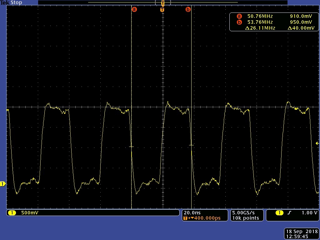
    The CSI-2 clock output waveform is shown below:

    666Mhz ( I took this on my slow scope but it gives the basic information that you want)

    The XIN_REFCLK is shown below:

    26.11Mhz..

    thanks,

    david

  • Hi David,

    I went into the lab and did the CSI clock measurement under the following condition:

    Ref Clock = 26MHz

    CSI_TX_SPEED = 1.6Gbps

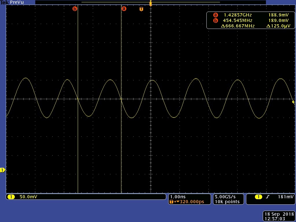
    Here's a scopeshot:

    As you can see, the CSI clock in my case runs at the expected ~833MHz.

    Best,

    Jiashow

  • Jiashow,

    Send me a register dump from the part when it is putting out 833Mhs, please.

    david

  • Hi David,

    You do not need to set any of the indirect registers mentioned in earlier documentation.

    For my setup, I changed register 0x1F to 1.6Gbps and 0x33 to enable CSI output. I'm using pat gen fixed colorbar 1280x720p30. Your CSI clock should be the same regardless of the resolution though.

    Reg = 0,0x0000,0x60
    Reg = 0,0x0001,0x00
    Reg = 0,0x0002,0x1E
    Reg = 0,0x0003,0x20
    Reg = 0,0x0004,0xD3
    Reg = 0,0x0005,0x01
    Reg = 0,0x0006,0x00
    Reg = 0,0x0007,0xFE
    Reg = 0,0x0008,0x1C
    Reg = 0,0x0009,0x10
    Reg = 0,0x000A,0x7A
    Reg = 0,0x000B,0x7A
    Reg = 0,0x000C,0x83
    Reg = 0,0x000D,0x09
    Reg = 0,0x000E,0x08
    Reg = 0,0x000F,0x7F
    Reg = 0,0x0010,0x00
    Reg = 0,0x0011,0x00
    Reg = 0,0x0012,0x00
    Reg = 0,0x0013,0x00
    Reg = 0,0x0014,0x00
    Reg = 0,0x0015,0x00
    Reg = 0,0x0016,0x00
    Reg = 0,0x0017,0x00
    Reg = 0,0x0018,0x00
    Reg = 0,0x0019,0x00
    Reg = 0,0x001A,0x00
    Reg = 0,0x001B,0x00
    Reg = 0,0x001C,0x00
    Reg = 0,0x001D,0x00
    Reg = 0,0x001E,0x04
    Reg = 0,0x001F,0x00
    Reg = 0,0x0020,0x30
    Reg = 0,0x0021,0x01
    Reg = 0,0x0022,0x00
    Reg = 0,0x0023,0x00
    Reg = 0,0x0024,0x00
    Reg = 0,0x0025,0x00
    Reg = 0,0x0026,0x00
    Reg = 0,0x0027,0x00
    Reg = 0,0x0028,0x00
    Reg = 0,0x0029,0x00
    Reg = 0,0x002A,0x00
    Reg = 0,0x002B,0x00
    Reg = 0,0x002C,0x00
    Reg = 0,0x002D,0x00
    Reg = 0,0x002E,0x00
    Reg = 0,0x002F,0x00
    Reg = 0,0x0030,0x00
    Reg = 0,0x0031,0x00
    Reg = 0,0x0032,0x00
    Reg = 0,0x0033,0x01
    Reg = 0,0x0034,0x40
    Reg = 0,0x0035,0x00
    Reg = 0,0x0036,0x00
    Reg = 0,0x0037,0x00
    Reg = 0,0x0038,0x00
    Reg = 0,0x0039,0x00
    Reg = 0,0x003A,0x00
    Reg = 0,0x003B,0x01
    Reg = 0,0x003C,0x14
    Reg = 0,0x003D,0x6F
    Reg = 0,0x003E,0x00
    Reg = 0,0x003F,0x40
    Reg = 0,0x0040,0x00
    Reg = 0,0x0041,0xA7
    Reg = 0,0x0042,0x71
    Reg = 0,0x0043,0x01
    Reg = 0,0x0044,0x00
    Reg = 0,0x0045,0x00
    Reg = 0,0x0046,0x00
    Reg = 0,0x0047,0x00
    Reg = 0,0x0048,0x00
    Reg = 0,0x0049,0x00
    Reg = 0,0x004A,0x00
    Reg = 0,0x004B,0x12
    Reg = 0,0x004C,0x00
    Reg = 0,0x004D,0x00
    Reg = 0,0x004E,0x02
    Reg = 0,0x004F,0x00
    Reg = 0,0x0050,0x00
    Reg = 0,0x0051,0x00
    Reg = 0,0x0052,0x00
    Reg = 0,0x0053,0x00
    Reg = 0,0x0054,0x00
    Reg = 0,0x0055,0x00
    Reg = 0,0x0056,0x00
    Reg = 0,0x0057,0x00
    Reg = 0,0x0058,0x1E
    Reg = 0,0x0059,0x00
    Reg = 0,0x005A,0x00
    Reg = 0,0x005B,0x00
    Reg = 0,0x005C,0x00
    Reg = 0,0x005D,0x00
    Reg = 0,0x005E,0x00
    Reg = 0,0x005F,0x00
    Reg = 0,0x0060,0x00
    Reg = 0,0x0061,0x00
    Reg = 0,0x0062,0x00
    Reg = 0,0x0063,0x00
    Reg = 0,0x0064,0x00
    Reg = 0,0x0065,0x00
    Reg = 0,0x0066,0x00
    Reg = 0,0x0067,0x00
    Reg = 0,0x0068,0x00
    Reg = 0,0x0069,0x00
    Reg = 0,0x006A,0x00
    Reg = 0,0x006B,0x00
    Reg = 0,0x006C,0x00
    Reg = 0,0x006D,0x7C
    Reg = 0,0x006E,0x88
    Reg = 0,0x006F,0x88
    Reg = 0,0x0070,0x2B
    Reg = 0,0x0071,0x2C
    Reg = 0,0x0072,0xE4
    Reg = 0,0x0073,0x00
    Reg = 0,0x0074,0x00
    Reg = 0,0x0075,0x00
    Reg = 0,0x0076,0x00
    Reg = 0,0x0077,0xC5
    Reg = 0,0x0078,0x00
    Reg = 0,0x0079,0x01
    Reg = 0,0x007A,0x00
    Reg = 0,0x007B,0x00
    Reg = 0,0x007C,0x20
    Reg = 0,0x007D,0x00
    Reg = 0,0x007E,0x00
    Reg = 0,0x007F,0x00
    Reg = 0,0x00A0,0x02
    Reg = 0,0x00A1,0x0F
    Reg = 0,0x00A2,0x00
    Reg = 0,0x00A3,0x00
    Reg = 0,0x00A4,0x08
    Reg = 0,0x00A5,0x19
    Reg = 0,0x00A7,0x00
    Reg = 0,0x00A8,0x00
    Reg = 0,0x00A9,0x00
    Reg = 0,0x00AA,0x00
    Reg = 0,0x00AB,0x00
    Reg = 0,0x00AC,0x00
    Reg = 0,0x00AD,0x00
    Reg = 0,0x00AE,0x00
    Reg = 0,0x00AF,0x00
    Reg = 0,0x00B0,0x00
    Reg = 0,0x00B1,0x0F
    Reg = 0,0x00B2,0x0A
    Reg = 0,0x00B3,0x08
    Reg = 0,0x00B4,0x25
    Reg = 0,0x00B5,0x00
    Reg = 0,0x00B6,0x18
    Reg = 0,0x00B7,0x00
    Reg = 0,0x00B8,0x8C
    Reg = 0,0x00B9,0x33
    Reg = 0,0x00BA,0x83
    Reg = 0,0x00BB,0x74
    Reg = 0,0x00BC,0x80
    Reg = 0,0x00BD,0x00
    Reg = 0,0x00BE,0x00
    Reg = 0,0x00BF,0x00
    Reg = 0,0x00D0,0x00
    Reg = 0,0x00D2,0x94
    Reg = 0,0x00D3,0x05
    Reg = 0,0x00D4,0x60
    Reg = 0,0x00D5,0xF2
    Reg = 0,0x00D6,0x00
    Reg = 0,0x00D7,0x00
    Reg = 0,0x00D8,0x00
    Reg = 0,0x00D9,0x00
    Reg = 0,0x00DA,0x00
    Reg = 0,0x00DB,0x00
    Reg = 0,0x00DC,0x00
    Reg = 0,0x00DD,0x00
    Reg = 0,0x00DE,0x00
    Reg = 0,0x00DF,0x00
    Reg = 0,0x00F0,0x5F
    Reg = 0,0x00F1,0x55
    Reg = 0,0x00F2,0x42
    Reg = 0,0x00F3,0x39
    Reg = 0,0x00F4,0x35
    Reg = 0,0x00F5,0x34
    Reg = 0,0x00F8,0x00
    Reg = 0,0x00F9,0x00
    Reg = 0,0x00FA,0x00
    Reg = 0,0x00FB,0x00

    Best,

    Jiashow

  • Jiashow & Antonio,

    If I do exactly what you described above I get 831.26Mhz out my CSI-2 clock port. Which is somewhat good news... I'll start putting my actual code back in to see if I can maintain the output clock. Something somewhere is breaking the things.

    I guess the net/net is that some other registers "do" have some impact on the CSI-2 clock output.  It's not "just" the input clock and register 0x33.

    david

  • David,

    Glad to hear that! Please keep us posted.

    Best,
    Jiashow
  • Hello,

    I assume the DS90UB954-Q1 is configured for the CSI-2 mode.

    For maximum bandwidth please ensure the CSI-2 Tx output is set to 4 lanes, and the CSI_PLL_CTL is programmed to 00.

    Regards,

    Liam

  • Hello Liam,

    Yes, CSI_PLL_CTL is set to 0x00. I have a 26Mhz oscillator coming in on the XIN_REFCLK. I also have it set to 4 lanes.

    If I set my board up like Jiashow did above (0x33 = 0x41, 0x1f = 0x00, and use a 954 test pattern) I can get the 832Mhz clock on the CSI-2 clock pins. I completely turn off the 953's, even disconnect the coax.. I can generate the 832Mhz clock speed if I do it all with the 954 test pattern generator.

    ...but not with my system setup...

    My actual system is Rx-0 & Rx-1 bringing in 4k30 data so when I put them back together in the 954 with interleaving forwarding I have a 4k60 frame. If I slow the clock at the source such that I am only sending data at a 46 fps rate everything works fine (because I don't need the full 1.664 Gbps data rate). When I speed the clock up (at the source - in front of the 953's) the 954 cannot handle the data rate at the CSI-2 output because I can only get 677Mhz out of the CSI-2 clock.

    david
  • This does not make sense as when the device is configured properly the CSI-2 Tx output clock of the 954 is independant of the Rx port inputs.
    Rgds,
  • Hi David,

    Could you try using pat gen on the 953 side and see if you could get the bandwidth? Also try running in round robin mode to see if it makes any differences?

    Best,
    Jiashow
  • Hi David,

    Did you say you are not seeing CSI output at all? Could you double check if your CSI output is enabled in reg 0x33?

    Best,
    Jiashow
  • I have CSI-2 output.
    I need to get the correct clock out of the CSI-2 port.
    Register 0x33 is correct.

    david
  • Hi David,

    Could you provide the script you are using?

    Best,
    Jiashow
  • Jiashow,

    I have a STM Cortex part running I2C to the 954. I just sent the code, a scope shot, and a register dump to Antonio. He will forward to you guys.

    thanks,
    david

  • Discussion moved offline.