This thread has been locked.

If you have a related question, please click the "Ask a related question" button in the top right corner. The newly created question will be automatically linked to this question.

SN65HVD3088E: Open the differential output voltage (VOD)of sn65hvd3088e

Part Number: SN65HVD3088E
Other Parts Discussed in Thread: SN65HVD3082E, THVD1450, THVD1550

Hello everyone!In my system, the servo driver and the encoder communicate through RS485.The baud rate of communication is 2.5M.The chip we chose is sn65hvd3088e. we compared the chip  TP75176E of 3peak company.We found that the differential output voltage of the  sn65hvd3088e is smaller than that of the chip.The encoder cable length is 15m

The test point is on the encoder side.

1. sn65hvd3088e


2.TP75176E

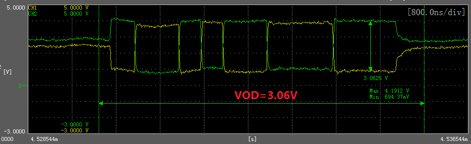
in application, we found that the greater the differential voltage, the greater the anti-interference performance. And it also adapte to different manufacturers encoder more.How do I increase the driving ability of the circuit to get a larger differential voltage? Is there any need to modify the circuit diagram? Can you recommend another chip?

  • Hi Tina,

    The output differential magnitude is a function of both the transceiver design (e.g., the driver output impedance and any internal voltage drops) as well as the termination resistance value (which would determine the amount of current output from the driver). For SN65HVD3082E, you could increase the differential output amplitude by increasing the termination resistance value. You could also remove (or decrease) the series 10-Ohm resistance values, since these will produce some attenuation of the differential signal.

    You could also try other transceiver devices. The THVD1450 would be a good option if you need higher VOD; it should provide about 4 V under this condition when VCC = 5 V.

    There are other ways to improve noise immunity without increasing the output amplitude as well. One example would be filtering of common-mode noise. I see you are using a common-mode choke, which is generally an effective technique. Another thing to try would be to use "split" termination, meaning that you could divide R7 into two 110-Ohm resistances in series with one another and place a filtering capacitor (~4.7 nF, for example) from the central connection point of these resistances to ground.

    You could also try other transceivers that were designed with better common-mode noise immunity. THVD1450 and THVD1550 are both examples of this. These devices were designed to tolerate the large noise levels that are often present on motor encoder communication lines while still maintaining data integrity. For more information, you may want to refer to this blog:

    e2e.ti.com/.../what-is-an-eft-part-2

    I hope this helps, and please let me know if you have any additional questions.

    Regards,
    Max
  • Thank you for your reply.I use the  "split" termination in the actual circuit.But I have a question, how do you determine the capacitance of the filtering capacitor?Why 4.7nF instead of other values?

  • Tina,

    As long as R74 and R78 are equal, the capacitance will only load the common-mode component of the bus and will not affect data communication. So, in general larger capacitance values can be seen as more effective at filtering (since they would decrease the corner frequency of the low-pass filtering that they are performing on common-mode noise). Depending on the expected noise frequencies, higher or lower capacitance values can be used. The drawbacks to a larger value are just things like package size and cost.

    Max