Hi Team,
We are failed to config 0xFE device, but for other I2C address is ok. And competitor-PCA9511ADP is also OK to config 0xFE.
We compare TI-TCA4311ADGKR and NXP-PCA9511ADP, the spec is all the same.
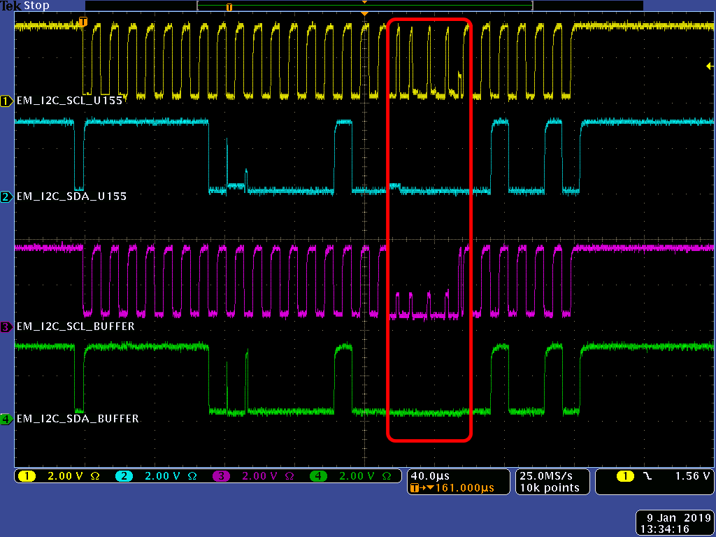
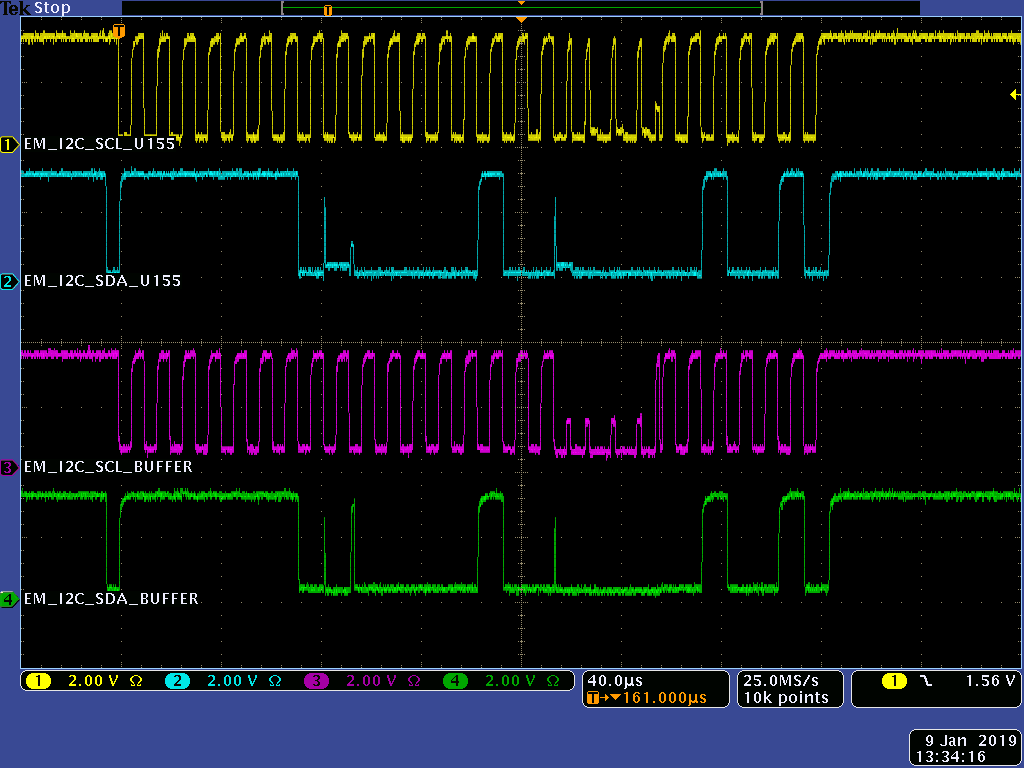
In below figure, we find CLK input (EM_I2C_SCL_U155) have clock in TCA4311ADGKR, and do not find CLK input EM_I2C_SCL_U155 in PCA9511ADP.
It looks these clocks cause IO module confused.
Please kindly give us some suggestion about where does the clock come from? And how to delete it.
Thanks
TI-TCA4311ADGKR:
PCA9511ADP:

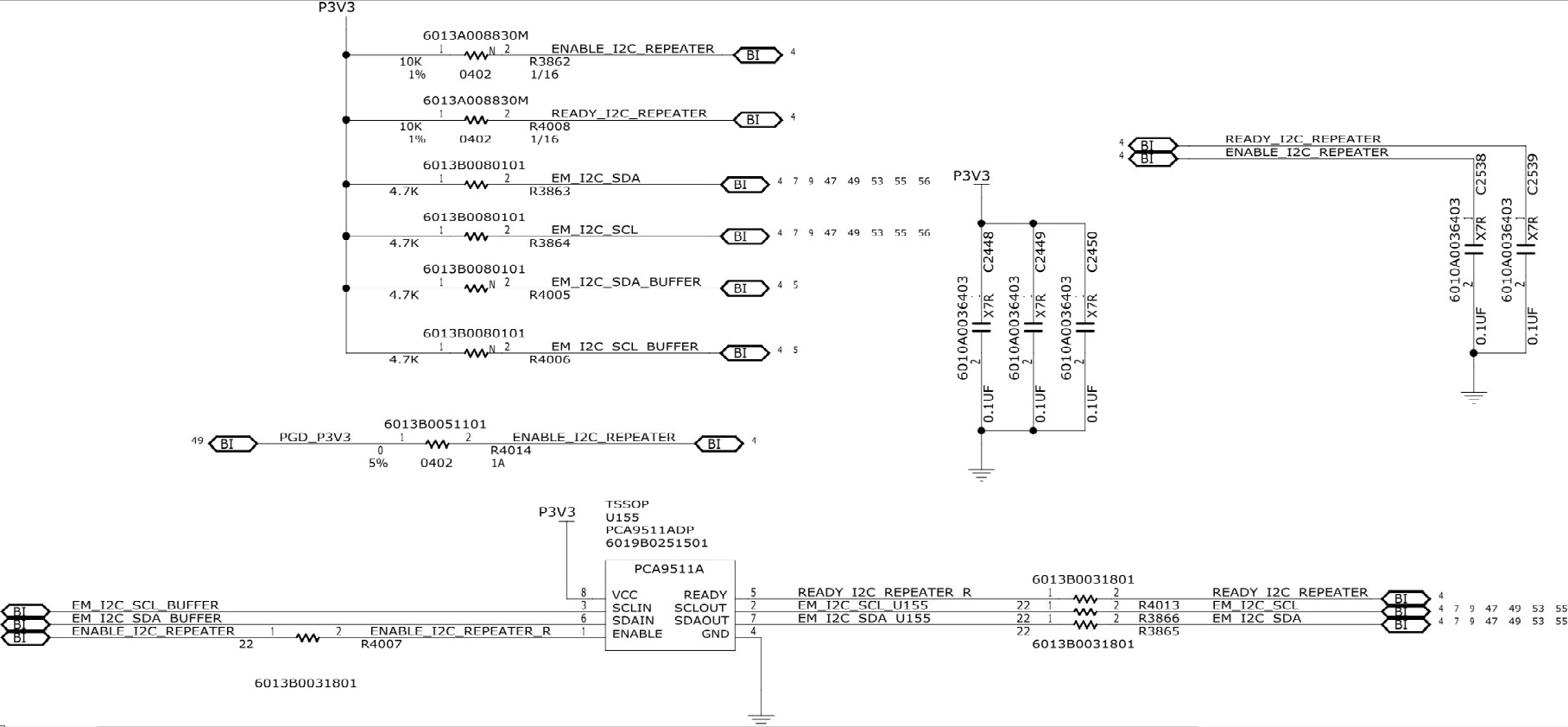
Schematic: