This thread has been locked.

If you have a related question, please click the "Ask a related question" button in the top right corner. The newly created question will be automatically linked to this question.

Large Overshoot and Undershoot from Differential Line Receivers -- DS26LS32AC

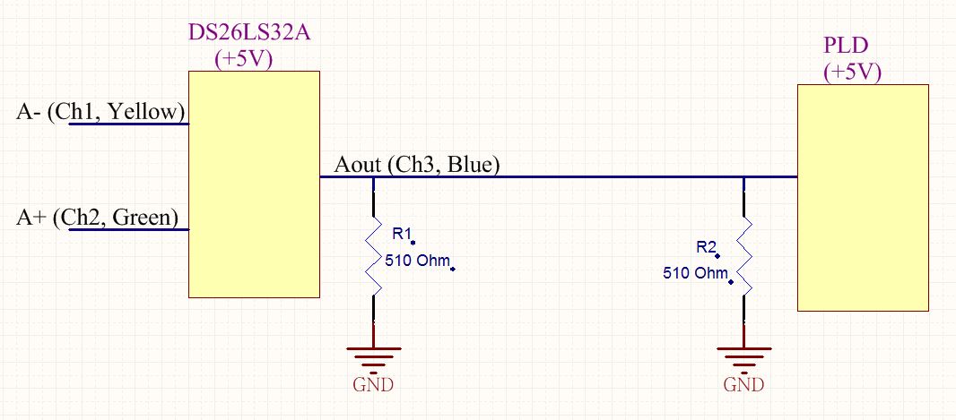
I use DS26LS32AC as a Differential to Single ended receiver, working under +5V.

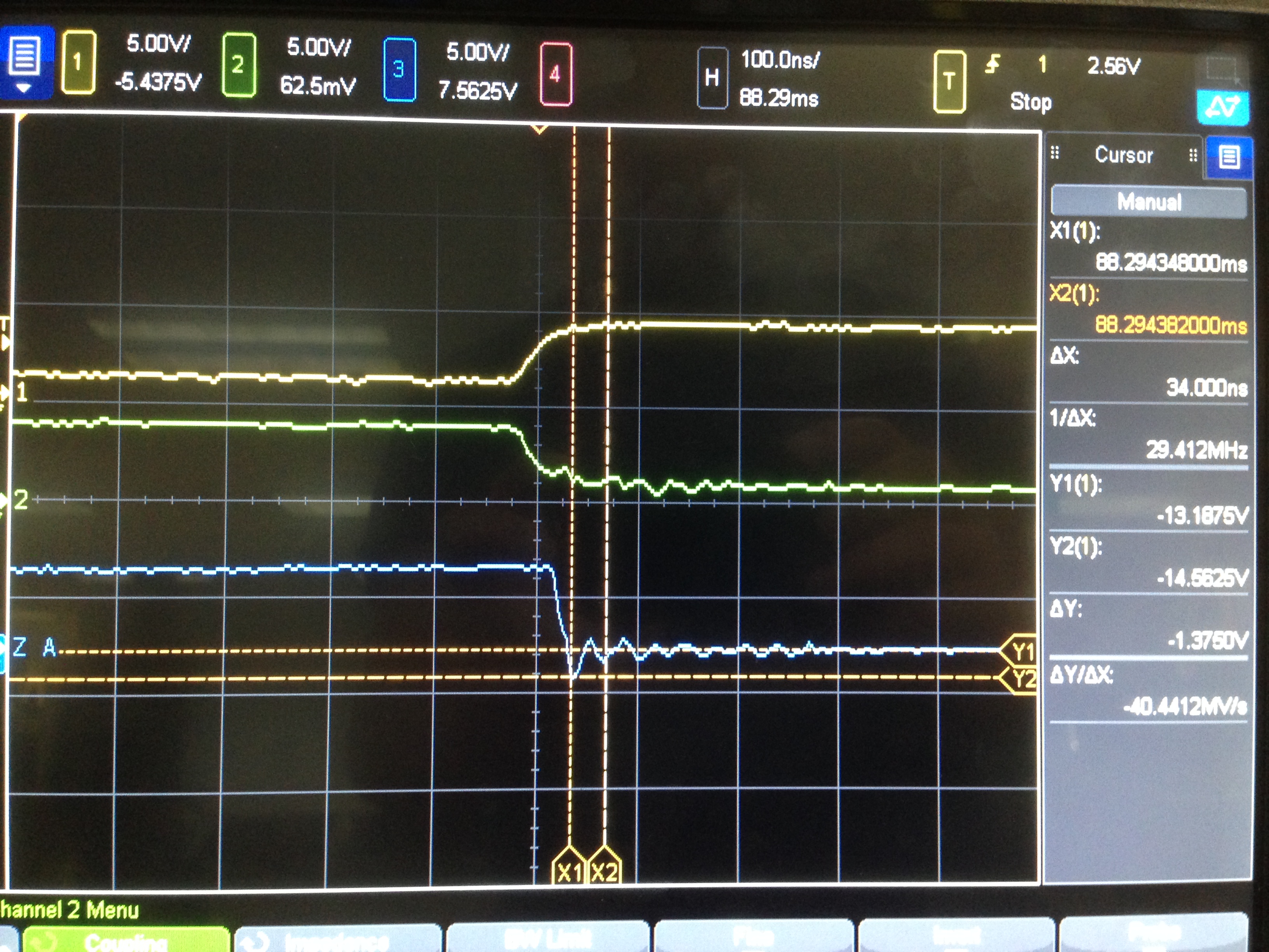
The two input differential signals are very clean with overshoot and undershoot of only around 20mV as square waves. But the single ended output has a overshoot of 1V and undershoot of 2V.


Why this chip has so large overshoot and undershoot? Generally, how overshoot and undershoot occur?

Thank you.

  • Moving to high speed interface forum.
  • Hi.

    The DS26LS31 device is not often associated with large undershoot or overshoot voltages.  Undershoot and overshoot can occur for a few different reasons, the primary reasons are output loading, output transmission line effects, and measurement technique and location.

    Since the output edge rate of the DS26LS31 is relatively slow, I would guess the most likely situation here is a combination of measurement and technique and no output load.

    What is the output load?

    What type of probing is used to measure the input and output waveforms?

    What is the frequency of the data?

    Please also post a picture of the input and output waveforms. 

    Best Regards,

    Lee

  • Hi Lee,

    Thank you for you reply.

    The maximum speed of the data is less than 10MHz.

    The following schematic is the structure of my test. ( I used a DS26LS32A, not DS26LS32AC, not sure of the difference).  The output of DS26LS32A is applied to a PLD that works as a buffer.

    Please note the original schematic has no R1 and R2 termination resistors. I place these two resistors to reduce the overshoot/undershoot during test. I got larger overshoot and undershoot without R1, R2.

    I measure differential inputs (A+, A-) and output (Aout) with a scope probe and clip shown in picture.


    Then I get the waveforms. The Yellow is Negative differential input, the Green is Positive differential input, the Blue is the Output.

    You can easily read the undershoot in the zoomed-in picture is around 1.4V.

    Please note, in this picture, the overshoot and undershoot is not significant because I placed R1 and R2 as terminations. If I remove these 2 resistors, the overshoot can be 1.3V and undershoot can be 1.8V.

    Thank you for your answer.

  • Hi with this type of probe the extra length in the GND connection and the signal connection reduce the probe bandwidth.  This tends to make waveforms have ringing and other artifacts which are not actually there.  Try to re-probe the signal with not extra lead clips to see if the waveform improves.

    Regards,

    Lee