This thread has been locked.

If you have a related question, please click the "Ask a related question" button in the top right corner. The newly created question will be automatically linked to this question.

PCA9543A: PCA9543A design topology

Part Number: PCA9543A
Other Parts Discussed in Thread: PCA9548A

Dear Team:

  Our customer woluld like to use our PCA9543A, and need our confirmation for this topology.

Hi Thomas


Could you please help to check I2C topology problem?

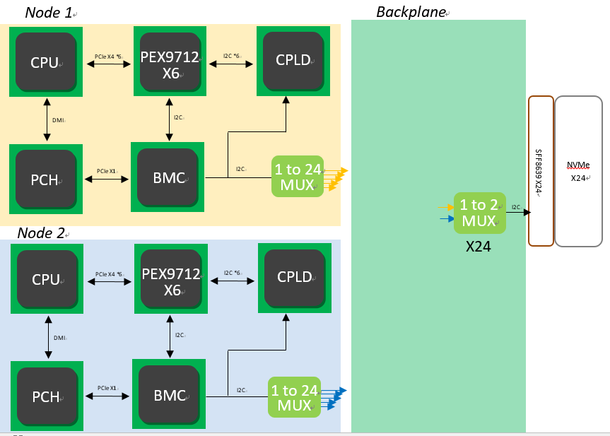
About 1 to 24 we plan put 3pcs PCA9548A and backplane side put 24pcs PCA9543A.

First we cascade twice mux on one I2C bus. Have any problem on topology?

Second could meet I2C parasitic capacitance limitation on 1 to 24 Mux.

When one time only enable one channel on one 8 channel mux IC ,other 8 channel Mux all be disabled the channel . How to calculate the I2C bus parasitic capacitance?

  • Hey Thomas,

    I'm having a hard time picturing how these two muxes are connected. Are you putting PCA9548A channel 0 of node1 and channel 0 of node 2 into a PCA9543A? Can you draw out a flow chart of how the master and slave are connected to each other?

    Also with the PCA9543A, you have only two address pins. At most you can have only 4 of these devices with unique addresses. After 4, you will have address conflicts.

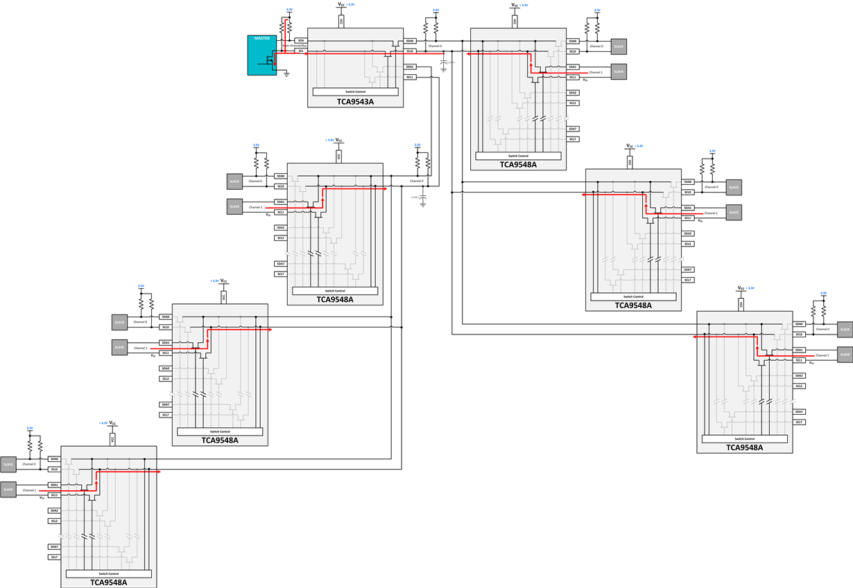
    I would really need to see how all of this connects before I rule this out as there are situations where this could work. If you have the PCA9548A channels turned on one at a time and then turn all other channels off. This could work.

    Thanks,
    -Bobby

    EDIT: Please consider our TCA products rather than PCA. The TCA are newer than PCA and usually accept wider voltage ranges among other things.

  • Hello Thomas,

    I have drawn what I think you are trying to do.  Can you confirm this is what you are trying to do?