This thread has been locked.

If you have a related question, please click the "Ask a related question" button in the top right corner. The newly created question will be automatically linked to this question.

PCA9306: Enable and VREF2 Problems

Part Number: PCA9306

I am having an issue with the PCA9306 not working correctly when I turn on an unrelated power supply.

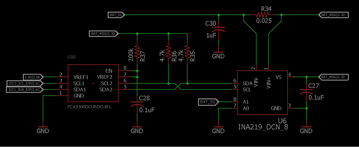
I am translating between 1.8V to a voltage that will vary between 3.2V and 4.2V. My design pretty much mimics Figure 7 from the datasheet. I also have 2.2k pull-ups on the 1.8V side located elsewhere on the schematic. My schematic is attached below:

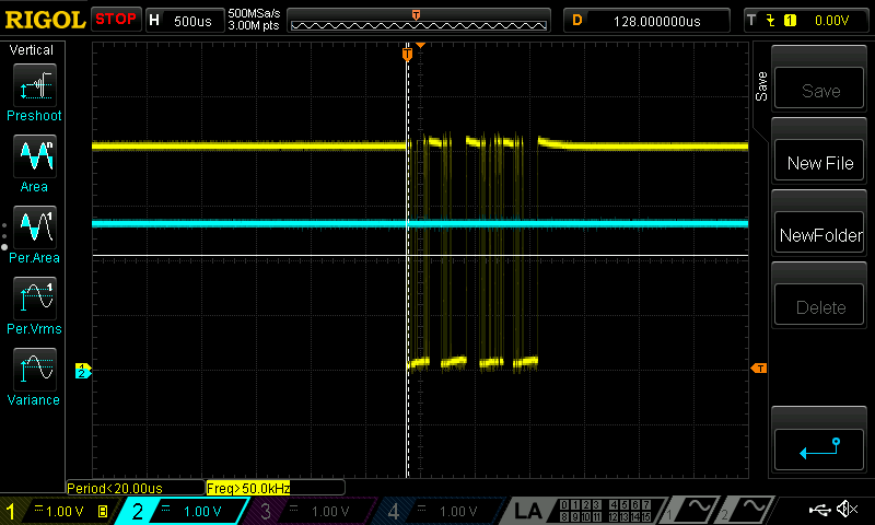
The PCA9306 works perfectly when the unrelated power supply is off. Enable and VREF2 are stable and are at a decent voltage level. See scope capture below (Blue- En / VREF2, Yellow - SDA):

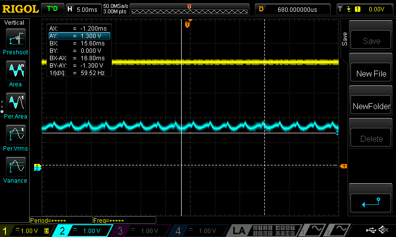
When the power supply is turned on and the current ramps up, the En / VREF2 start to behaving erratically. See scope capture below (Blue- En / VREF2):

En / VREF2 have dropped from approximately 3.6V down to minimum of 1.3V. En / VREF2 start to droop more and more until the PCA9306 turns off and the SCL and SDA lines stop toggling  I have tried different capacitance on En / VREF2 from 1000pF to 0.1uF. I have also tried changing the resistor from 50k to 300k. The scope capture above is with a 50k. From the schematic above, BAT_4002, 1.8V, and gnd are all stable and not fluctuating.

Why would turning on an unrelated power supply affect the performance of the PCA9306 especially when all the rails provided to the PCA9306 are stable?

Thanks,

Tyler 

  • Hello Tyler,

    Turning on an unrelated power supply should not affect this node.  What is the other supply and have you looked at the layout?  \

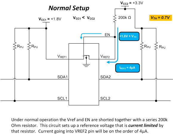
    Vref1, Vref2, and EN pin are used to setup a reference for turning on and off the pass fet for SDA and SCL.  Something must be pulling Vref2-EN connection down. 

    ~1.3V is suspiciously one diode drop away from 1.8V.  I would start looking their.  I can review your schematic and layout if you need help reviewing it.  If it is sensitive information you can send me the project files to me via email.

    francis.houde@ti.com

    -Francis Houde

  • Hi Francis,

    I sent you an email with a bunch more details of the design. Also, where did that "Normal Setup" image come from and what threshold is the "Vth = 0.7V" referring to?

    Just in case any others come across this and have some input:

    1. The other supply is a Cuk, that is either powered off 4.2 of 12V. As this supply provides more current to the output load, EN / VREF2 are affected more.

    2. The layout is a 4-layer board with copper pours for 1.8V, 4.2V, and GND. All the vias and components are tightly placed next to each other with reasonable spacing to avoid cross-talk and other issues.

    3. That ~1.3V is worse case when the Cuk is providing the most current. If I lower the current then 1.3V will rise. That makes me think I can rule out a diode drop.

    The part that completely confuses me is if the 1.8V, 4.2V, and GND (only power signals going to the PCA9306) are all stable, how can adjusting a power supply from a different circuit affect it. I've measured all the power nodes and except for the minor switching noise from the Cuk, they are a constant voltage. The only thing I can think of is coupling from the Cuk's coupled inductor, but it is a shielded.

    Also, is there a lower resistance limit to the current limiting resistor? As I lower the resistance, my Cuk can provide more current. What would happen if I put a 20k or lower? It seems like the current would go to 40uA, but would that really damage the chip?

    Thanks again!
  • Hello Tyler,
    I don't seem to have gotten your email. Can you resend it to me. Let me know the title of the email so I can search for it easily. I checked my junk and spam folders and I didn't see it there either.
    -Francis Houde
  • Francis,
    I am also curious if a different value than 200K would work. Could say a 121K work? 200K is not a value we typically use and stock.

    Thanks!
  • Hey Jay,

    Just chiming in here.

    "Could say a 121K work? "
    -This will work, the 200k resistor is there to limit current. Using 121k would just mean a little bit more power consumption.

    -Bobby
  • I just thought I would wrap this up and let everyone know how I fixed the problem.

    The problem ended up being resolved by placing a 0.1uF on VREF1 as well. This was kind of misleading because the PCA9306 schematic only specifies placing a cap on VREF2 and EN. Also, a lot of the EVM schematics are different from each other which was also confusing.

    Thank you everyone for looking into this!

    -Tyler