For Isolation related questions:
Please post a question on the new Digital Isolators Forum.
This thread has been locked.
If you have a related question, please click the "Ask a related question" button in the top right corner. The newly created question will be automatically linked to this question.
Part Number: AM26C31
Hello all,
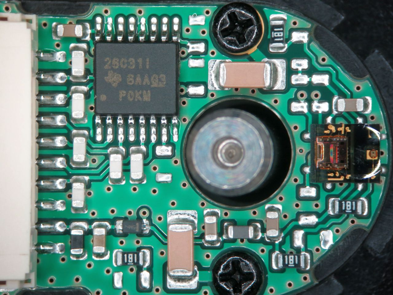
is the usage of the output and inverted output at the AM26C31 mandatory?
In my design I am using only the output to drive the pullup and the low pass on the receiver site and left the inverted output open.
Can this lead to malfunctions on the AM26C31?
Thx for your support.
Regards, Burkhard
In reply to Max Robertson:
Hello Max,Thanks for your quick response.The background of my question is an erroneous behavior that we rarely observed in conjunction with a stepper motor optical encoder.I reengineered the circuit of the encoder and found out that the encoder manufacturer use the AM26C31I as output line driver.I connect the motor encoder (channels A and B -> as I mentioned before not the inverted signals /A and /B) via a cable to a pcb where I merge the encoder signal with some other signals and use a different cable (SMC-ribbon cable) to bring the signals to the mainboard. On the mainboard the encoder signals have a pull up resistor of 2k7 to 3.3 V and then go via a low passes (100R/1n) to inputs of a SN74LVC3G17 (VCC=3.3 V). The output signals of the SN74LVC3G17 are processed by the FPGA then.On the encoder electronics the AM26C31I is supplied with 5 V. The high level output voltage of the AM26C31I is approx. 3.4 V as I expected according to the data sheet 6.5 Electrical Characteristics: AM26C31C and AM26C31I.The erroneous behavior that I rarely observe is that the low level is not driven correctly below the low level trigger voltage of the SN74LVC3G17. This behavior lasts from several 100 microsecondes to some milliseconds and then disappears. I saw that on one channel but our FPGA signal processing flags us error where both channels A and B of the encoder are influences at the same time. But this behavior I have not seen with my oscilloscope.To make the situation clearer, it would be possible to support you with schematic excerpts and scope plots, if you are interrested.Thank you in advance for your efforts.Regards, Burkhard
In reply to Burkhard Seyferth:
Hi Max,
You are right with the comparsion between A = Y and /A = Z to the data sheet's nomencla-ture. I attached you first a photo from the encoder pcb with the AM26C31I and my circuit analysis sketch of the encoder circuit. I give you also some oscilloscope waveform captures of the erroneous behavior. There you can see, what it means when I describe it with "no proper low level". I'll hope this can clarify the problem I am facing. Regards, Burkhard
C1= Encoder signal from channel A of the motor encoder
C1= A, C2= B Encoder signals from channels A and B of the motor encoder
Max,unfortunately the occurring of the error is very seldom, so investigations are very difficult. If you look to the zoom of the third waveform from my former answer, it seems to me, that the "distorted" driving low is not so strong (different time constants) as in normal case. What could be the reason for that? But I share your thoughts and if a periodically short to a low impedance source, like VCC, would be the cause, in this case the output of the AM26C31 should try to switch this source to low. For what reason ever the waveform plot shows, it cannot drive the low level in this case. If the reason would be the limited drive capability ot the AM26C31, then an excessive current should flow into the AM26C31. To exclude this, I measured the VCC current to the motor encoder and the GND current too. I would expect if the AM26C31 shorts a low impedance source with its output to GND and the capability of its output would exceeded, the current should flow into the output of the AM26C31 and back via encoder GND to the source. I'll hope you can follow my thoughts. But neither the VCC nor the GND current of the encoder showed abnormal values under normal and erroneous conditions. That leads me to the conclusion, that an "additional" resistor between the output of the AM26C31 and my pull-up resistor (2k7) would lead to the recorded waveforms. The value of the additional resistor could have the magnitude of 5k5. I added you an overview sketch of my arrangement. The error is unfortunately not limited to one single device. I am facing several error messages from the field, where some devices seem affected with this failure. At the moment I can't do anything because the error on may setup is not present. Devices delivered back from the field, don't show the failure when I try to do further measurements. Any further suggestions to find the root cause of the behavior are welcome. Regards, Burkhard
C1= Mainboard Signal TABLE_ENC_B @ R118
C4= GND current flowed back from NOE1 to BExtension Board, Cable NOE1 to BExtension Board -> wire1,8 and10 in current clamp (20 mA/Div)
C4= VCC current flowed to NOE1 from BExtension Board, Cable NOE1 to BExtension Board -> wire 9 in current clamp (20 mA/Div)
NOE1 is the motor encoder which uses the AM26C31 as line driver.