

Hi All,
I wonder the C# source code of the 'General Purpose GUI' can be obtained.
In the 'General Purpose GUI Overview' document, the software was mentioned as 'freeware'. So, it seems like the source code would be also available.
Thank you!

This thread has been locked.
If you have a related question, please click the "Ask a related question" button in the top right corner. The newly created question will be automatically linked to this question.
Hi All,
I wonder the C# source code of the 'General Purpose GUI' can be obtained.
In the 'General Purpose GUI Overview' document, the software was mentioned as 'freeware'. So, it seems like the source code would be also available.
Thank you!

Eric,
The source code for the General Purpose GUI is not very clean would be difficult to migrate to a different project. For this reason TI has kept this code closed but freeware.
A better starting point would be the GUI for the
Digital Power Experimenter’s Kit. It is located in the board specific software download for this kit at http://www.ti.com/f28xkits. Many of the other development kits include the source C# project for their GUIs as well.
Thanks,
Brett

hi,
i am working on digital power control on a kit custom made board
i want to use GUI template
i want to know if there is any documentation about that as i could not find it
thanks in advance
Muhammad,
Unfortunately, the GUI project source does not have any documentation specifically on it.
The "QSG-GeneralPurposeGUI.pdf" document explains how to edit the C2000 software to allow it to connect up to a GUI. This document can be found at http://www.ti.com/f28xkits within the package downloaded when you click the "Baseline Installer" link.
Thank you,
Brett
i,
a small problem
i initilized every thing right but i ma getting error on symbol
CommsOKflg during linking,may be because it cant locate the fil e where its defined any coments
Waqar,
I would recommend taking a look at the FlashingLeds example project that goes within the Baseline installer, see above for a link. It has comms enabled and should help you to find the issue.
The CommsOKflg should be initialized as a variable inside the Main file and initialized to 0. The CommsOKflg flag should set itself to 0 if comms are not enabled by the SciCommsGui file.
Thanks,
Brett

can't help with this specific question, but we did recently distribute the source for one of these GUIs, the latest used on the multi-DCDC color lighting kit. It's in controlSUITE
C:\ti\controlSUITE\development_kits\Multi-DCDC-Color-LED-Kit_v1.0\~GUI\Source
We are also using CrossHairs Embedded GUI creation tool on some kits (DRV8412-C2-KIT) and we will likely release the source to that style on the next revision as well.
Dear ChrisClearman,
I have tested the General purpose GUI with one of project. Its works nicely.
I am not familiar with C# programming. so I can't make my own user interface with C#.
Can I use Lab-VIEW for user interface design. Any examples on it. Or can give any details about
the protocol of communication between General purpose GUI and Piccolo controller.
Regards
Ittoop
HI,
Agreed that if the C2000 MCU have a general comni interface with Lab-VIEW or Matlab. Looking forward to seeing the development release if possible.
BR,
Barry
TI has a JTAG based debugger interface that we release to tools third parties like Mathworks. So they can interface to our JTAG, build proejcts, and download. We use the same thing for GUI Composer - which is included in CCSv5.3+ - and allows you to build graphical instrumentation interfaces which communicate through JTAG. There will also be a UART interface for GUI Composer shortly.

toop and Barry,
Attached is some code (java and LabVIEW) that glues a LabVIEW vi to an instance of DSS (debug server scripting - a headless version of CCS that is included with you CCS installation). This is by no means robust, complete, well-documented, or easy to use, and this is definitely not officially supported by TI in any way, but if you really want to attach C28x code to a LabVIEW GUI, this is at least a starting point.
@Devin,
Thank you - thank you - thank you.
And - hope your fate does not echo poor Edward's - and that you have better accommodations than Moscow's (famed) air "in-transit" terminal. (in something...)
Promise to visit - w/shiny hack-saw blade - entombed w/in giant hero sandwich... (suspect you can hack the aged alarm...)
cb1,
lol. Just to be clear though, this is not the source of any TI released GUI; this is some glue code that has been useful internally for automating certain development tasks.
@Devin,
Understand - did not expect more - always thrilled to receive same - again great thanks...
Under separate cover - do find/accept: a) alarm schematic, b) alarm's Fortran code, c) internal map showing any/all "duct-work," and "back-up" saw-blades - just in case... (and perhaps semi-eaten ... i.e. "tested" hero...)
And - to be equally clear - our group is not the source of any perceived "escape materials" - although may have been past useful internally...
Dear Chris,
I heard there is GUI Composer when I was googleing yesterday. I tried some LED flashing demo following the video. It is amazing news known from you that there will be a a UART version.
Since I only find limited information on TI wiki and E2E forum about GUI Composer I am looking forward to the more release.
Thanks a lot for your information
BR,
Barry
Dear Devin,
Its an amazing code. I will try it! thanks a lot.
Thanks a lot for your information
BR,
Barry
Dear Chris,
May I ask what is the max. variable refresh rate of the GUI Composer? Is it able to display a 50Hz Sine wave?
BR,
Barry
I've sent this over to the GUI composer developers to see if they have a real value. It certainly will display a 50 Hz sinewave, but not sure exactly how many points will be used. The higher frequency current waveforms we display are much higher than that and look quite good for development purposes.
Hello Barry,
Depending on your device, application load, whether you use UART or JTAG driver with real time access, the numbers can be different.
By default the target code that handles the UART requests is configured for 9600 baud rate, therefore you won’t be able to transfer more that 900 bytes per second.
It is possible to configure higher rates but I haven’t played with it yet. But again, your target application need to be able to handle the higher load.
JTAG connection is faster than 9600 BPS but I don’t have the exact number. We have done applications that transfer 4000 bytes per seconds with no problem.
On the GUI Composer side we have two different graphs that can be hooked up:
LineGraph – you need to buffer the data on the target side in an array and each second the whole array will be transferred and displayed.
ScalarGraph – the data is stored in one variable on the target and it is accumulated in the graph each second.
Even though you can change the one second interval to a higher frequency, to handle tens and hundreds of points per second most probably you will need to use LineGraph – buffer the data in an array in the target program.
I hope this helps.
Dobrin
Dear Dobrin,
Thanks for your information. At least I have an initial guessing on the limitation of the GUI Composer. If I have to display more than one 50Hz signals, the tasks would be more difficult.
Our project is still ongoing. I hope I can share more when it comes to this stage.
And please forgive me I have one more question. Can the graph data on the GUI side export as some text format like CSV so that I can easily to use those result for reports and documentations?
Thank you again.
BR,
Barry
It is a requested feature and we are considering adding it but no commitment to a specific release yet.
Can you describe how would you like the feature to work in your case?
Dear Dobrin,
We are now building a power inverter with 220Vac 50Hz output with 20A current.
We need the GUI Composer to prepare the GUI for control.
Initially, I want to know if it is able to display the real time waveforms of inverter voltage, current, DC input current, powers etc… But it seems that it is too difficult to achieve.
So now, I think I will display the real time rms values of those parameters on the GUI and plot the graphs of parameters versus time. We would like to export those data and plot it using Matlab.
Attached is a part of the CSV I exported from PowerSIM results. The simulation time is start from 1sec and there are 15 sets data. I wonder if GUI Composer can produce the data like this format. Thanks!
BR,
Barry
Hi Barry,
Just to add to Dobrin's response. GUI Composer will refresh all visible widgets on a fixed interval (currently set at 1s). This refresh interval can be adjusted to something more frequent, but the frequency is somewhat dependent on the amount of data that needs to be transferred. In past experiments with JTAG, you probably will not be able to go below 100-200ms for a refresh cycle. Assuming each refresh requires a few words of data. If you have large arrays that need to be transferred (e.g. when plotting a graph), then that frequency will need to be adjusted.
With above scheme, one option is to buffer data on the target and continuously update it on a frequent basis, then update GUI less frequently(i.e. initiate target to host PC transfer). I am not sure whether this is feasible for your application.
I took a look at your .csv file. I don't think there would be an issue graphing this data. If you had data buffers (i.e. arrays) for each of your variables (e.g. IS1, Vgrid), etc, then you would need to use LineGraph widget. Then you could choose whether all values should be displayed in a single graph or multiple graphs.
As Dobrin mentioned, we do not have support for saving to .csv file. However, I think his question were more related to how data should be saved on the host. Some options that we are considering
a) allow user to save data currently displayed in the graph (something like right click on a graph and export to csv)
b) Configure host side to store all data refreshed into a log file, with some sort of a record idea. You data seems to fall into this section.
c) some configurable option where data to be logged is chosen
Most of our reply deals with what we call program model. i.e. host side asks for data (pulls data from target). We have another mode of support where target pushes data out to the host. We call this streaming model as target streams the data continuously. This might fit your scenario better. Current implementation requires more GUI Application development effort. In this case the limitations on data transfer would be much more limited by UART and how fast the target can push data out without impacting actual application processing.
martin
Hi Martin,
May I ask does the GUI composer v.5.5 support for this feature or not?
And where can I find the update log of of each version of GUI composers?
Thanks,
Barry
GUI Composer will refresh all visible widgets on a fixed interval (currently set at 1s). This refresh interval can be adjusted to something more frequent, but the frequency is somewhat dependent on the amount of data that needs to be transferred. In past experiments with JTAG, you probably will not be able to go below 100-200ms for a refresh cycleMartinS said:
How do you adjust the refresh interval of the GUI composer?
Can it be adjusted also for standalone exported projects?
Thanks.
To set the refresh rate to 2 seconds you can add an entry to the app.json file.
{
"serverBindName": "$refresh_interval",
"options": {
"dataType": "Long",
"defaultValue" : "2000"
}
},
Alternatively, if you want a widget that controls the rate just bind that widget to "$refresh_interval".
Keep in mind that since it is not a supported feature GUI Composer can remove that record when you edit the application’s HTML file. You need to open app.json in a text editor and make sure it is there after each save.
Dear Dorbrin
May I ask you some question about GUI composer?
Now I use TMS320F28335 for a motor control experiment. During the debug process, I need to observe 8 variables at same time. Originally I use DCA7714 to observe the variable. I transfer the variable through SPI communication to DA and observe them by a scope. Then I could record and analyze. However the scope only has 4 channels. But now I need observe 8 variables. So I wonder whether I could use linegraph widget to finish my task.
This task has real-time request. The 8 variables are floating point and they are refreshed at 10KHz, which is also the frequency of Main ISR. (interrupt void MainISR(void))
I feel TMS320F28335 use JTAG connection. But I don’t know whether it is fast enough to transfer 8 floating point variables.
Another problem is I encounter failure when I use ScalarGraph widget.
First I try display only one variable. I utilize a project designed by TI, provided in controlsuite.
ti\controlSUITE\development_kits\HVMotorCtrl+PfcKit_v2.1\HVACI_Sensorless_2833x
In this project I bind a global variable rg1.Out to value0 of the scalarlinegraph. This variable is expected to generate a ramp. I set the Buffer Length to 200. However when I run the project, the graph always has some glitch, which should not appear.

When I change to another computer, it is even worse. There is no ramp curve at all. The only difference is the OS of the computer. The previous computer is Win XP. This one is Win7. The emulator is same, XDS100V2USB.

I feel strange about this phenomenon. I don’t know what mistake I make. Have you ever meet such condition? Could I trouble you give me some suggestion?
Hello Xin,
I’d like to make sure I understood your questions. Please correct me if I did not get them right?
Question 1:
I am using a TMS320F2833 with a JTAG connection. I want to create a GUI Composer application that have multiple Line Graphs in it.
The amount of data that need to be transferred every second to display the information I need is:
10,000 * 8 *sizeof(float). Let’s assume sizeof float in the hardware is 4 byte.
Can the XDS100V2USB handle transfer rate of 300 Kilobytes per second?
Answer:
No. XDS100V2 does not have that much throughput. Let alone there are overheads of drawing the graphs, handing each received bytes. etc.
In a ideal situation the transfer rate is 480 Kbits per seconds. http://processors.wiki.ti.com/index.php/XDS100#XDS100v2_Features
So we are order of magnitude off, just by looking at pure throughput.
Question 2:
If I use a scalar graph the data shown is not what I expected. The graph also varies if I run the app on another computer. What went wrong?
Answer 2:
Scalar Graphs accumulate the value of the variable they are bound to each second and show the history of that variable over time.
To be used property the target has to run enough time so the accumulated data that makes sense.
In the first pictures you the target is halted. In the second picture there is no even a debug session.
Can you provide pictures that the target is running and has been running for enough amount of time?
Also, are you sure the values considered glitches are not the real values sampled at a specific time?
Can you create a very simple project ( preferably on a simulator ) that demonstrate the issue?
Regards
Dobrin
Dear Dobrin
Really appreciate for your reply. I am so sorry to disturb you with some low level question.
Question1 is right.
I need transfer 300 kilobytes data per second. Since XDS100V2 can’t handle so much data, whether we could have other method to realize such task? Whether xds560v2, which is produced by Spectrum Digital, could survive?
If xds560v2 can not support either, and I still wish to observe 8 floating point variables at same time for debug, whether there is any possible solution? Could I trouble you to give me some suggestion?
By the way I read the website you give me.
http://processors.wiki.ti.com/index.php/XDS100#XDS100v2_Features
It shows that XDS100V2 supports 480 Mbit/s not 480 Kbit/s. And I check on Google. The speed of USB2.0 is 480 Mbit/s.
So if its speed reaches 480 Mbit/s, it equals to 15Mbyte/s. 15Mbyte/s=15*1024Kbyte/s=15360 Kbyte/s.
And the transfer rate we need is 10,000 * 8 *4 byte=320Kbyte/s. So I feel if the transfer rate is really 480 Mbit/s, XDS100V2 could transfer 8 floating point variables.
Whether the USB speed mentioned on that website doesn’t refer to the transfer rate?
Question 2
As you suggested, I catch some picture that the target is running. The target has run for a while, about 15 second.
At my PC, Win XP system, the graph looks good. We could observe the ramp wave clearly, although there are still some glitches.
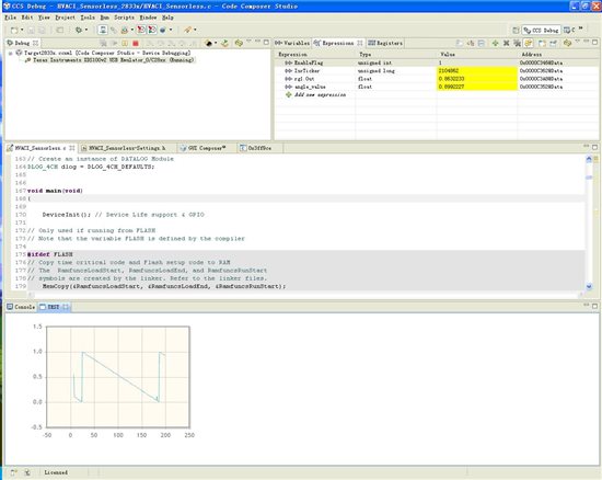

However, when I run the same program at my laptop, OS is Win 7, the graph looks terribly.

I feel strange. The program is totally same. And the hardware is also same. The only difference is that I install GUI Composer Runtime(CCSv5.4) for my laptop.
I down load it from
http://processors.wiki.ti.com/index.php/Category:GUI_Composer
I don’t know whether it is the reason that my laptop can’t draw correct graph.
And in your reply you also ask “Also, are you sure the values considered glitches are not the real values sampled at a specific time?”
So I have a test, I let the variable equals to 0.5, a constant value. In the graph it indeed becomes a straight line.

However, the program in my PC and the program in my laptop are totally same. The graph should be same at least. I feel puzzled.
Question 3
May ask a extremely low question? What is the difference between “silicon real-time mode” and “polite real-time mode”? when I debug their enable button are close to each other. I don’t which one I should use.
Really thank you for your help.
Yours
Xin
Hello Xin,
Yes, you are right: I mixed Megabit with Kilobits so looks like the row USB transfer is not a limiting factor.But I still would not bet much that we will be able to display, even transfer that much data – 320 Kbytes per second.Before I give you more exact answer I would like do some experimentation myself.
But let’s back up a bit:
What application do you really want to create?
We have two types of graph:
LineGraph – at one pass it transfer a whole array from the target and display it.
ScalarGraph – you bind it to a single number variable
It accumulates the value in the GUI Composer application.
On each refresh only transfers 1 float number
Do you really need that much data transferred to the application – 10000*8*4?
What will your graphs show to the user? Even if we assume that you can transfer that much data to your GUI composer application what will you do with it. You won’t be able to show eight graphs each showing ten thousand points – you don’t have that much screen resolution.
Can we first define what will your application will do and then go back and see if we need to show something different to the users. May be we want to scale the data on the target, buffer it in arrays and only show these arrays that have much lower resolution?
Some other notes:
By default GUI applications update all data once per second.If you add a text box and bind it to $refresh_interval you can control the refresh rate.May be if you set it to a bigger value than 1000, for example 5000 ( it is milliseconds) you laptop will work better. Can you try that?
I will try to reproduce the program you are seeing with the single value graph.Can you send me both you program and your GUI Composer project.BTW, all snapshot you are showing me are from Code Composer Studio – not from the GUI Composer Runtime, which version of GUI Composer Runtime does not matter. What is your Code Composer Studio version?
About the real time mode, here is an e-mail snippet from Darian Sale:
Regarding realtime mode, my advice is to stay away unless they know what it is – polite mode doesn’t really work unless your application sets up critical sections/interrupts, and their application is not doing that if they don’t know what there is. Realtime-capable targets can now perform rude-realtime accesses without entering any “mode”. They should be using that. For more details, check out: http://focus.ti.com/docs/training/catalog/events/event.jhtml?sku=OLT212002 (this is actually out of date, but the information about realtime mode is still accurate, but it’s all I found in a short search
I hope you answer your question.
Regards
Dobrin
Dear Dobrin
Really thank you for your patient for my problem.
I have the same feeling as you. Although USB could have a high speed, other links, which has low speed, will finally decide the transfer rate.
1 Please allow me to explain my application.
What I really want to do is debug my program with the graph.
I am working on my induction motor drive experiment. My algorithm has some bug. I need debug the program while the motor is running. In the past I use DA to solve this problem. I design an analog output card with DAC7714, which has 4 output channels and can generate voltage from -10V to 10V. DAC7714 can be connected with 28335 through SPI communication. The variable can be transferred to DAC and shown as a voltage signal. Then I could record those voltage signals with oscilloscope. Based on oscillation graph I can analyze those 4 variables at the same time instance and find the bug.
Since the refresh rate of my target is 10 KHz, SPI communication of DAC7714 is fast enough to handle 4 16-bit date. The following graph is recorded by scope.

Oscilloscope only has 4 channels; however, I need observe 8 variables at same time. So I want to try GUI composer. I don’t know whether there is any alternate method for such real-time debug. I feel experts from TI must have better method, when they with motor drive program debug.
My CCS version is 5.4.0.00091. The CCS installed on my PC and my laptop is same.
Whether there is any document gives specific instruction of GUI composer.
I search on the internet. I only find an introductory video about GUI Composer.
http://software-dl.ti.com/dsps/dsps_public_sw/sdo_ccstudio/guicomposer/gc_intro/gc_intro.html
And I also find a tutorial, a PPT file, which provides a step by step guide for how to create a simple GUI Composer Application.
Both of them are from the wiki of TI.
http://processors.wiki.ti.com/index.php/Category:GUI_Composer
I am so sorry for my searching ability. I can’t find more details about widgets and how to use these widgets. Especially the LineGraph widget, I really want to find an example to show how to use LineGraph wiget.
Furthermore you suggest we add a text box and bind it to $refresh_interval then we can control the refresh rate. May I ask how do you know this trick? In which document can we find such details?
Please allow me to explain my test.
I directly use a motor control program provided in controlSUITE to test the GUI composer.
The project location is as following:
C:\ti\controlSUITE\development_kits\HVMotorCtrl+PfcKit_v2.1\HVACI_Sensorless_2833x\
After I import this project, I modify the head-file “HVACI_Sensorless-Settings.h”.
#define BUILDLEVEL LEVEL1
It is at line 20 of this h file.
In the main C file “HVACI_Sensorless.c”, I define a global variable
float32 angle_value;
I use this variable to connect to GUI graph.
In the main interrupt function interrupt void MainISR(void), we could find level 1.
Variable rg1.Out will generate a ramp wave. Since rg1.Out is IQ format, I give its value to the global variable angle_value, which is float format. angle_value is bound to value 0 in scalarlinegraph.
I would like to send my program and my GUI project.
May I ask some details?
1. Should I send you the entire project of that motor control program or just the C file, which includes main function? If you need the whole project, could I have your email? It is more convenient to send a large attachment.
2. I search in the workspace and only find a folder named “.GUIComposerWS”. Whether GUI COMPOSER project is totally in it? Whether I should send this folder to you?
3. May I ask what does BTW mean? You ever mention it your last post.
/* ==============================================================================
System Name:  	HVACI_Sensorless

File Name:	  	HVACI_Sensorless.C

Description:	Primary system file for the Real Implementation of Sensorless
          		Field Orientation Control for Induction Motors

				Supports F2803x(fixed point) and F2833x(floating point)
=================================================================================  */

// Include header files used in the main function

#include "PeripheralHeaderIncludes.h"
#include "HVACI_Sensorless-Settings.h"
#include "IQmathLib.h"
#include "HVACI_Sensorless.h"
#include <math.h>


#ifdef FLASH
#pragma CODE_SECTION(MainISR,"ramfuncs");
#pragma CODE_SECTION(OffsetISR,"ramfuncs");
#endif

// Prototype statements for functions found within this file.
interrupt void MainISR(void);
interrupt void OffsetISR(void);
void DeviceInit();
void MemCopy();
void InitFlash();
void HVDMC_Protection(void);


// State Machine function prototypes
//------------------------------------
// Alpha states
void A0(void);	//state A0
void B0(void);	//state B0
void C0(void);	//state C0

// A branch states
void A1(void);	//state A1
void A2(void);	//state A2
void A3(void);	//state A3

// B branch states
void B1(void);	//state B1
void B2(void);	//state B2
void B3(void);	//state B3

// C branch states
void C1(void);	//state C1
void C2(void);	//state C2
void C3(void);	//state C3

// Variable declarations
void (*Alpha_State_Ptr)(void);	// Base States pointer
void (*A_Task_Ptr)(void);		// State pointer A branch
void (*B_Task_Ptr)(void);		// State pointer B branch
void (*C_Task_Ptr)(void);		// State pointer C branch

// Used for running BackGround in flash, and ISR in RAM
extern Uint16 *RamfuncsLoadStart, *RamfuncsLoadEnd, *RamfuncsRunStart;


int16	VTimer0[4];			// Virtual Timers slaved off CPU Timer 0 (A events)
int16	VTimer1[4]; 		// Virtual Timers slaved off CPU Timer 1 (B events)
int16	VTimer2[4]; 		// Virtual Timers slaved off CPU Timer 2 (C events)
int16	SerialCommsTimer;

// Global variables used in this system

float32 angle_value;


Uint16 OffsetFlag=0;
_iq offsetA=0;
_iq offsetB=0;
_iq offsetC=0;
_iq K1=_IQ(0.998);		//Offset filter coefficient K1: 0.05/(T+0.05);
_iq K2=_IQ(0.001999);	//Offset filter coefficient K2: T/(T+0.05);
extern _iq IQsinTable[];
extern _iq IQcosTable[];

_iq VdTesting = _IQ(0.2);			// Vd reference (pu)
_iq VqTesting = _IQ(0.2);			// Vq reference (pu)
_iq IdRef = _IQ(0.1);				// Id reference (pu)
_iq IqRef = _IQ(0.05);				// Iq reference (pu)
_iq SpeedRef = _IQ(0.3);			// Speed reference (pu)

float32 T = 0.001/ISR_FREQUENCY;    // Samping period (sec), see parameter.h

Uint32 IsrTicker = 0;
Uint16 BackTicker = 0;
Uint16 lsw=0;
Uint16 TripFlagDMC=0;				//PWM trip status

// Default ADC initialization
int ChSel[16]   = {0,0,0,0,0,0,0,0,0,0,0,0,0,0,0,0};
int	TrigSel[16] = {5,5,5,5,5,5,5,5,5,5,5,5,5,5,5,5};
int ACQPS[16]   = {8,8,8,8,8,8,8,8,8,8,8,8,8,8,8,8};

int16 DlogCh1 = 0;
int16 DlogCh2 = 0;
int16 DlogCh3 = 0;
int16 DlogCh4 = 0;

volatile Uint16 EnableFlag = FALSE;

Uint16 SpeedLoopPrescaler = 10;      // Speed loop prescaler
Uint16 SpeedLoopCount = 1;           // Speed loop counter

// Instance rotor flux and speed estimations
ACIFE fe1 = ACIFE_DEFAULTS;
ACISE se1 = ACISE_DEFAULTS;

// Instance the constant calculations for rotor flux and speed estimations
ACIFE_CONST fe1_const = ACIFE_CONST_DEFAULTS;
ACISE_CONST se1_const = ACISE_CONST_DEFAULTS;

// Instance a QEP interface driver
QEP qep1 = QEP_DEFAULTS;

// Instance a Capture interface driver
CAPTURE cap1 = CAPTURE_DEFAULTS;

// Instance a few transform objects (ICLARKE is added in SVGEN module)
CLARKE clarke1 = CLARKE_DEFAULTS;
PARK park1 = PARK_DEFAULTS;
IPARK ipark1 = IPARK_DEFAULTS;

// Instance PI regulators to regulate the d and q  axis currents, and speed
PI_CONTROLLER pi_spd = PI_CONTROLLER_DEFAULTS;
PI_CONTROLLER pi_id  = PI_CONTROLLER_DEFAULTS;
PI_CONTROLLER pi_iq  = PI_CONTROLLER_DEFAULTS;

// Instance a PWM driver instance
PWMGEN pwm1 = PWMGEN_DEFAULTS;

// Instance a PWM DAC driver instance
PWMDAC pwmdac1 = PWMDAC_DEFAULTS;

// Instance a Space Vector PWM modulator. This modulator generates a, b and c
// phases based on the d and q stationery reference frame inputs
SVGEN svgen1 = SVGEN_DEFAULTS;

// Instance a ramp controller to smoothly ramp the frequency
RMPCNTL rc1 = RMPCNTL_DEFAULTS;

//	Instance a ramp(sawtooth) generator to simulate an Anglele
RAMPGEN rg1 = RAMPGEN_DEFAULTS;

//	Instance a phase voltage calculation
PHASEVOLTAGE volt1 = PHASEVOLTAGE_DEFAULTS;

// Instance a speed calculator based on QEP
SPEED_MEAS_QEP speed1 = SPEED_MEAS_QEP_DEFAULTS;

// Instance a speed calculator based on capture Qep (for eQep of 280x only)
SPEED_MEAS_CAP speed2 = SPEED_MEAS_CAP_DEFAULTS;

// Create an instance of DATALOG Module
DLOG_4CH dlog = DLOG_4CH_DEFAULTS;


void main(void)
{

	DeviceInit(); // Device Life support & GPIO

// Only used if running from FLASH
// Note that the variable FLASH is defined by the compiler

#ifdef FLASH
// Copy time critical code and Flash setup code to RAM
// The  RamfuncsLoadStart, RamfuncsLoadEnd, and RamfuncsRunStart
// symbols are created by the linker. Refer to the linker files.
	MemCopy(&RamfuncsLoadStart, &RamfuncsLoadEnd, &RamfuncsRunStart);

// Call Flash Initialization to setup flash waitstates
// This function must reside in RAM
	InitFlash();	// Call the flash wrapper init function
#endif //(FLASH)

   // Waiting for enable flag set
   while (EnableFlag==FALSE)
    {
      BackTicker++;
    }

// Timing sync for background loops
// Timer period definitions found in device specific PeripheralHeaderIncludes.h
	CpuTimer0Regs.PRD.all =  mSec1;		// A tasks
	CpuTimer1Regs.PRD.all =  mSec5;		// B tasks
	CpuTimer2Regs.PRD.all =  mSec50;	// C tasks

// Tasks State-machine init
	Alpha_State_Ptr = &A0;
	A_Task_Ptr = &A1;
	B_Task_Ptr = &B1;
	C_Task_Ptr = &C1;

// Initialize PWM module
    pwm1.PeriodMax = SYSTEM_FREQUENCY*1000000*T/2;  // Prescaler X1 (T1), ISR period = T x 1
    pwm1.HalfPerMax=pwm1.PeriodMax/2;
    pwm1.Deadband  = 2.0*SYSTEM_FREQUENCY;     	    // 120 counts -> 2.0 usec for TBCLK = SYSCLK/1
    PWM_INIT_MACRO(1,2,3,pwm1)

// Initialize PWMDAC module
	pwmdac1.PeriodMax=500;		   	// @60Mhz, 1500->20kHz, 1000-> 30kHz, 500->60kHz
	pwmdac1.HalfPerMax=pwmdac1.PeriodMax/2;
	PWMDAC_INIT_MACRO(6,pwmdac1) 	// PWM 6A,6B
	PWMDAC_INIT_MACRO(7,pwmdac1) 	// PWM 7A,7B

// Initialize DATALOG module
    dlog.iptr1 = &DlogCh1;
    dlog.iptr2 = &DlogCh2;
    dlog.iptr3 = &DlogCh3;
    dlog.iptr4 = &DlogCh4;
    dlog.trig_value = 0x1;
    dlog.size = 0x0C8;
    dlog.prescalar = 5;
    dlog.init(&dlog);

// Initialize ADC for DMC Kit Rev 1.1
	ChSel[0]=1;		// Dummy meas. avoid 1st sample issue Rev0 Picollo*/
	ChSel[1]=1;		// ChSelect: ADC A1-> Phase A Current
	ChSel[2]=9;		// ChSelect: ADC B1-> Phase B Current
	ChSel[3]=3;		// ChSelect: ADC A3-> Phase C Current
	ChSel[4]=15;	// ChSelect: ADC B7-> Phase A Voltage
	ChSel[5]=14;	// ChSelect: ADC B6-> Phase B Voltage
	ChSel[6]=12;	// ChSelect: ADC B4-> Phase C Voltage
	ChSel[7]=7;		// ChSelect: ADC A7-> DC Bus  Voltage

// Initialize ADC module
	ADC_MACRO_INIT(ChSel,TrigSel,ACQPS)

// Initialize QEP module
    qep1.LineEncoder = 2048;
    qep1.MechScaler = _IQ30(0.25/qep1.LineEncoder);
    qep1.PolePairs = POLES/2;
    qep1.CalibratedAngle = 0;
	QEP_INIT_MACRO(1,qep1)

// Initialize CAP module
	CAP_INIT_MACRO(1)

// Initialize the Speed module for QEP based speed calculation
    speed1.K1 = _IQ21(1/(BASE_FREQ*T));
    speed1.K2 = _IQ(1/(1+T*2*PI*5));  // Low-pass cut-off frequency
    speed1.K3 = _IQ(1)-speed1.K2;
    speed1.BaseRpm = 120*(BASE_FREQ/POLES);

// Initialize the Speed module for capture eQEP based speed calculation (low speed range)
    speed2.InputSelect = 1;
 	speed2.BaseRpm = 120*(BASE_FREQ/POLES);
	speed2.SpeedScaler = 60*(SYSTEM_FREQUENCY*1000000/(1*2048*speed2.BaseRpm));

// Initialize the RAMPGEN module
    rg1.StepAngleMax = _IQ(BASE_FREQ*T);

// Initialize the aci flux estimator constants module
	fe1_const.Rs = RS;
	fe1_const.Rr = RR;
	fe1_const.Ls = LS;
	fe1_const.Lr = LR;
	fe1_const.Lm = LM;
	fe1_const.Ib = BASE_CURRENT;
	fe1_const.Vb = BASE_VOLTAGE;
	fe1_const.Ts = T;
	ACIFE_CONST_MACRO(fe1_const)

// Initialize the aci flux estimator module
 	fe1.K1 = _IQ(fe1_const.K1);
 	fe1.K2 = _IQ(fe1_const.K2);
 	fe1.K3 = _IQ(fe1_const.K3);
 	fe1.K4 = _IQ(fe1_const.K4);
 	fe1.K5 = _IQ(fe1_const.K5);
 	fe1.K6 = _IQ(fe1_const.K6);
 	fe1.K7 = _IQ(fe1_const.K7);
 	fe1.K8 = _IQ(fe1_const.K8);
    fe1.Kp = _IQ(2.8);
    fe1.Ki = _IQ(T/0.45);

// Initialize the aci speed estimator constants module
	se1_const.Rr = RR;
	se1_const.Lr = LR;
	se1_const.fb = BASE_FREQ;
	se1_const.fc = 3;
	se1_const.Ts = T;
	ACISE_CONST_MACRO(se1_const)

// Initialize the  aci speed estimator module
 	se1.K1 = _IQ(se1_const.K1);
 	se1.K2 = _IQ21(se1_const.K2);
 	se1.K3 = _IQ(se1_const.K3);
 	se1.K4 = _IQ(se1_const.K4);
 	se1.BaseRpm = 120*BASE_FREQ/POLES;

// Initialize the PI module for Id
    pi_spd.Kp=_IQ(2.0);
	pi_spd.Ki=_IQ(T*SpeedLoopPrescaler/0.5);
	pi_spd.Umax =_IQ(0.95);
	pi_spd.Umin =_IQ(-0.95);

// Initialize the PI module for Iq
	pi_id.Kp=_IQ(1.0);
	pi_id.Ki=_IQ(T/0.004);
	pi_id.Umax =_IQ(0.3);
	pi_id.Umin =_IQ(-0.3);

// Initialize the PI module for speed
	pi_iq.Kp=_IQ(1.0);
	pi_iq.Ki=_IQ(T/0.004);
	pi_iq.Umax =_IQ(0.8);
	pi_iq.Umin =_IQ(-0.8);

//  Note that the vectorial sum of d-q PI outputs should be less than 1.0 which refers to maximum duty cycle for SVGEN.
//  Another duty cycle limiting factor is current sense through shunt resistors which depends on hardware/software implementation.
//  Depending on the application requirements 3,2 or a single shunt resistor can be used for current waveform reconstruction.
//  The higher number of shunt resistors allow the higher duty cycle operation and better dc bus utilization.
//  The users should adjust the PI saturation levels carefully during open loop tests (i.e pi_id.Umax, pi_iq.Umax and Umins) as in project manuals.
//  Violation of this procedure yields distorted current waveforms and unstable closed loop operations which may damage the inverter.

//Call HVDMC Protection function
	HVDMC_Protection();

// Reassign ISRs.

	EALLOW;	// This is needed to write to EALLOW protected registers
	PieVectTable.EPWM1_INT = &OffsetISR;
	EDIS;

// Enable PIE group 3 interrupt 1 for EPWM1_INT
    PieCtrlRegs.PIEIER3.bit.INTx1 = 1;

// Enable CNT_zero interrupt using EPWM1 Time-base
    EPwm1Regs.ETSEL.bit.INTEN = 1;   // Enable EPWM1INT generation
    EPwm1Regs.ETSEL.bit.INTSEL = 2;  // Enable interrupt period event
    EPwm1Regs.ETPS.bit.INTPRD = 1;   // Generate interrupt on the 1st event
	EPwm1Regs.ETCLR.bit.INT = 1;     // Enable more interrupts

// Enable CPU INT3 for EPWM1_INT:
	IER |= M_INT3;
// Enable global Interrupts and higher priority real-time debug events:
	EINT;   // Enable Global interrupt INTM
	ERTM;	// Enable Global realtime interrupt DBGM

// IDLE loop. Just sit and loop forever:
	for(;;)  //infinite loop
	{
		// State machine entry & exit point
		//===========================================================
		(*Alpha_State_Ptr)();	// jump to an Alpha state (A0,B0,...)
		//===========================================================

	}
} //END MAIN CODE

//=================================================================================
//	STATE-MACHINE SEQUENCING AND SYNCRONIZATION FOR SLOW BACKGROUND TASKS
//=================================================================================

//--------------------------------- FRAMEWORK -------------------------------------
void A0(void)
{
	// loop rate synchronizer for A-tasks
	if(CpuTimer0Regs.TCR.bit.TIF == 1)
	{
		CpuTimer0Regs.TCR.bit.TIF = 1;	// clear flag

		//-----------------------------------------------------------
		(*A_Task_Ptr)();		// jump to an A Task (A1,A2,A3,...)
		//-----------------------------------------------------------

		VTimer0[0]++;			// virtual timer 0, instance 0 (spare)
		SerialCommsTimer++;
	}

	Alpha_State_Ptr = &B0;		// Comment out to allow only A tasks
}

void B0(void)
{
	// loop rate synchronizer for B-tasks
	if(CpuTimer1Regs.TCR.bit.TIF == 1)
	{
		CpuTimer1Regs.TCR.bit.TIF = 1;				// clear flag

		//-----------------------------------------------------------
		(*B_Task_Ptr)();		// jump to a B Task (B1,B2,B3,...)
		//-----------------------------------------------------------
		VTimer1[0]++;			// virtual timer 1, instance 0 (spare)
	}

	Alpha_State_Ptr = &C0;		// Allow C state tasks
}

void C0(void)
{
	// loop rate synchronizer for C-tasks
	if(CpuTimer2Regs.TCR.bit.TIF == 1)
	{
		CpuTimer2Regs.TCR.bit.TIF = 1;				// clear flag

		//-----------------------------------------------------------
		(*C_Task_Ptr)();		// jump to a C Task (C1,C2,C3,...)
		//-----------------------------------------------------------
		VTimer2[0]++;			//virtual timer 2, instance 0 (spare)
	}

	Alpha_State_Ptr = &A0;	// Back to State A0
}


//=================================================================================
//	A - TASKS (executed in every 1 msec)
//=================================================================================
//--------------------------------------------------------
void A1(void) // SPARE (not used)
//--------------------------------------------------------
{
	if(EPwm1Regs.TZFLG.bit.OST==0x1)
	TripFlagDMC=1;      // Trip on DMC (halt and IPM fault trip )

	//-------------------
	//the next time CpuTimer0 'counter' reaches Period value go to A2
	A_Task_Ptr = &A2;
	//-------------------
}

//-----------------------------------------------------------------
void A2(void) // SPARE (not used)
//-----------------------------------------------------------------
{

	//-------------------
	//the next time CpuTimer0 'counter' reaches Period value go to A3
	A_Task_Ptr = &A3;
	//-------------------
}

//-----------------------------------------
void A3(void) // SPARE (not used)
//-----------------------------------------
{

	//-----------------
	//the next time CpuTimer0 'counter' reaches Period value go to A1
	A_Task_Ptr = &A1;
	//-----------------
}


//=================================================================================
//	B - TASKS (executed in every 5 msec)
//=================================================================================

//----------------------------------- USER ----------------------------------------

//----------------------------------------
void B1(void) // Toggle GPIO-00
//----------------------------------------
{

	//-----------------
	//the next time CpuTimer1 'counter' reaches Period value go to B2
	B_Task_Ptr = &B2;
	//-----------------
}

//----------------------------------------
void B2(void) //  SPARE
//----------------------------------------
{

	//-----------------
	//the next time CpuTimer1 'counter' reaches Period value go to B3
	B_Task_Ptr = &B3;
	//-----------------
}

//----------------------------------------
void B3(void) //  SPARE
//----------------------------------------
{

	//-----------------
	//the next time CpuTimer1 'counter' reaches Period value go to B1
	B_Task_Ptr = &B1;
	//-----------------
}


//=================================================================================
//	C - TASKS (executed in every 50 msec)
//=================================================================================

//--------------------------------- USER ------------------------------------------

//----------------------------------------
void C1(void) 	// Toggle GPIO-34
//----------------------------------------
{

	if(EPwm1Regs.TZFLG.bit.OST==0x1)			// TripZ for PWMs is low (fault trip)
	  { TripFlagDMC=1;
	  }


	GpioDataRegs.GPBTOGGLE.bit.GPIO34 = 1;	   // Turn on/off LD3 on the controlCARD

	//-----------------
	//the next time CpuTimer2 'counter' reaches Period value go to C2
	C_Task_Ptr = &C2;
	//-----------------

}

//----------------------------------------
void C2(void) //  SPARE
//----------------------------------------
{

	//-----------------
	//the next time CpuTimer2 'counter' reaches Period value go to C3
	C_Task_Ptr = &C3;
	//-----------------
}


//-----------------------------------------
void C3(void) //  SPARE
//-----------------------------------------
{

	//-----------------
	//the next time CpuTimer2 'counter' reaches Period value go to C1
	C_Task_Ptr = &C1;
	//-----------------
}


//MainISR
interrupt void MainISR(void)
{

// Verifying the ISR
    IsrTicker++;

// =============================== LEVEL 1 ======================================
//	  Checks target independent modules, duty cycle waveforms and PWM update
//	  Keep the motors disconnected at this level
// ==============================================================================

#if (BUILDLEVEL==LEVEL1)

// ------------------------------------------------------------------------------
//  Connect inputs of the RMP module and call the ramp control macro
// ------------------------------------------------------------------------------
    rc1.TargetValue = SpeedRef;
	RC_MACRO(rc1)

// ------------------------------------------------------------------------------
//  Connect inputs of the RAMP GEN module and call the ramp generator macro
// ------------------------------------------------------------------------------
    rg1.Freq = rc1.SetpointValue;
	RG_MACRO(rg1)

// ------------------------------------------------------------------------------
//  Connect inputs of the INV_PARK module and call the inverse park trans. macro
//	There are two option for trigonometric functions:
//  IQ sin/cos look-up table provides 512 discrete sin and cos points in Q30 format
//  IQsin/cos PU functions interpolate the data in the lookup table yielding higher resolution.
// ------------------------------------------------------------------------------
    ipark1.Ds = VdTesting;
    ipark1.Qs = VqTesting;

	//ipark1.Sine  =_IQ30toIQ(IQsinTable[_IQtoIQ9(rg1.Out)]);
    //ipark1.Cosine=_IQ30toIQ(IQcosTable[_IQtoIQ9(rg1.Out)]);

	ipark1.Sine=_IQsinPU(rg1.Out);
    ipark1.Cosine=_IQcosPU(rg1.Out);
	IPARK_MACRO(ipark1)

 // TEST FOR GUI COMPOSER
   angle_value = rg1.Out;
//	angle_value = ipark1.Sine;


// ------------------------------------------------------------------------------
//  Connect inputs of the SVGEN_DQ module and call the space-vector gen. macro
// ------------------------------------------------------------------------------
  	svgen1.Ualpha = ipark1.Alpha;
 	svgen1.Ubeta = ipark1.Beta;
	SVGENDQ_MACRO(svgen1)

// ------------------------------------------------------------------------------
//  Connect inputs of the PWM_DRV module and call the PWM signal generation macro
// ------------------------------------------------------------------------------
    pwm1.MfuncC1 = svgen1.Ta;
    pwm1.MfuncC2 = svgen1.Tb;
    pwm1.MfuncC3 = svgen1.Tc;
	PWM_MACRO(1,2,3,pwm1)							// Calculate the new PWM compare values

// ------------------------------------------------------------------------------
//    Connect inputs of the PWMDAC module
// ------------------------------------------------------------------------------
	pwmdac1.MfuncC1 = svgen1.Ta;
    pwmdac1.MfuncC2 = svgen1.Tb;
    PWMDAC_MACRO(6,pwmdac1)	  						// PWMDAC 6A, 6B

    pwmdac1.MfuncC1 = svgen1.Tc;
    pwmdac1.MfuncC2 = svgen1.Tb-svgen1.Tc;
	PWMDAC_MACRO(7,pwmdac1)

// ------------------------------------------------------------------------------
//    Connect inputs of the DATALOG module
// ------------------------------------------------------------------------------
    DlogCh1 = _IQtoQ15(svgen1.Ta);
    DlogCh2 = _IQtoQ15(svgen1.Tb);
    DlogCh3 = _IQtoQ15(svgen1.Tc);
    DlogCh4 = _IQtoQ15(svgen1.Tb-svgen1.Tc);

#endif // (BUILDLEVEL==LEVEL1)

// =============================== LEVEL 2 ======================================
//	  Level 2 verifies the analog-to-digital conversion, offset compensation,
//    clarke/park transformations (CLARKE/PARK), phase voltage calculations
// ==============================================================================

#if (BUILDLEVEL==LEVEL2)

// ------------------------------------------------------------------------------
//  Connect inputs of the RMP module and call the ramp control macro
// ------------------------------------------------------------------------------
    rc1.TargetValue = SpeedRef;
	RC_MACRO(rc1)

// ------------------------------------------------------------------------------
//  Connect inputs of the RAMP GEN module and call the ramp generator macro
// ------------------------------------------------------------------------------
    rg1.Freq = rc1.SetpointValue;
	RG_MACRO(rg1)

// ------------------------------------------------------------------------------
//  Measure phase currents, subtract the offset and normalize from (-0.5,+0.5) to (-1,+1).
//	Connect inputs of the CLARKE module and call the clarke transformation macro
// ------------------------------------------------------------------------------
	#ifdef DSP2833x_DEVICE_H
	clarke1.As=((AdcMirror.ADCRESULT1)*0.00024414-offsetA)*2*0.909; // Phase A curr.
	clarke1.Bs=((AdcMirror.ADCRESULT2)*0.00024414-offsetB)*2*0.909; // Phase B curr.
	#endif														   // ((ADCmeas(q12)/2^12)-offset)*2*(3.0/3.3)

	#ifdef DSP2803x_DEVICE_H
	clarke1.As = _IQmpy2(_IQ12toIQ(AdcResult.ADCRESULT1)-offsetA); // Phase A curr.
	clarke1.Bs = _IQmpy2(_IQ12toIQ(AdcResult.ADCRESULT2)-offsetB); // Phase B curr.
	#endif														   // (ADCmeas(q12->q24)-offset)*2

	CLARKE_MACRO(clarke1)

// ------------------------------------------------------------------------------
//  Connect inputs of the PARK module and call the park trans. macro
// ------------------------------------------------------------------------------
	park1.Alpha = clarke1.Alpha;
	park1.Beta = clarke1.Beta;
	park1.Angle = rg1.Out;
	park1.Sine = _IQsinPU(park1.Angle);
	park1.Cosine = _IQcosPU(park1.Angle);
	PARK_MACRO(park1)

// ------------------------------------------------------------------------------
//	Connect inputs of the INV_PARK module and call the inverse park trans. macro
// ------------------------------------------------------------------------------
    ipark1.Ds = VdTesting;
    ipark1.Qs = VqTesting;
	ipark1.Sine=park1.Sine;
    ipark1.Cosine=park1.Cosine;
	IPARK_MACRO(ipark1)

// ------------------------------------------------------------------------------
//  Connect inputs of the VOLT_CALC module and call the phase voltage calc. macro
// ------------------------------------------------------------------------------
	#ifdef DSP2833x_DEVICE_H
	volt1.DcBusVolt = ((AdcMirror.ADCRESULT7)*0.00024414)*0.909; // DC Bus voltage meas.
    #endif														 // (ADCmeas(q12)/2^12)*(3.0V/3.3V)

    #ifdef DSP2803x_DEVICE_H
	volt1.DcBusVolt = _IQ12toIQ(AdcResult.ADCRESULT7);	     	 // DC Bus voltage meas.
    #endif

    volt1.MfuncV1 = svgen1.Ta;
    volt1.MfuncV2 = svgen1.Tb;
    volt1.MfuncV3 = svgen1.Tc;
    PHASEVOLT_MACRO(volt1)

// ------------------------------------------------------------------------------
//  Connect inputs of the SVGEN_DQ module and call the space-vector gen. macro
// ------------------------------------------------------------------------------
  	svgen1.Ualpha = ipark1.Alpha;
 	svgen1.Ubeta = ipark1.Beta;
  	SVGENDQ_MACRO(svgen1)

// ------------------------------------------------------------------------------
//  Connect inputs of the PWM_DRV module and call the PWM signal generation macro
// ------------------------------------------------------------------------------
    pwm1.MfuncC1 = svgen1.Ta;
    pwm1.MfuncC2 = svgen1.Tb;
    pwm1.MfuncC3 = svgen1.Tc;
	PWM_MACRO(1,2,3,pwm1)							// Calculate the new PWM compare values

// ------------------------------------------------------------------------------
//    Connect inputs of the PWMDAC module
// ------------------------------------------------------------------------------
	pwmdac1.MfuncC1 = svgen1.Ta;
    pwmdac1.MfuncC2 = svgen1.Tb;
    PWMDAC_MACRO(6,pwmdac1)	  						// PWMDAC 6A, 6B

    pwmdac1.MfuncC1 = svgen1.Tc;
    pwmdac1.MfuncC2 = svgen1.Tb-svgen1.Tc;
	PWMDAC_MACRO(7,pwmdac1)		  					// PWMDAC 7A, 7B

// ------------------------------------------------------------------------------
//  Connect inputs of the DATALOG module
// ------------------------------------------------------------------------------
    DlogCh1 = _IQtoQ15(clarke1.As);
    DlogCh2 = _IQtoQ15(clarke1.Bs);
    DlogCh3 = _IQtoQ15(svgen1.Ta);
    DlogCh4 = _IQtoQ15(volt1.VphaseA);


#endif // (BUILDLEVEL==LEVEL2)

// =============================== LEVEL 3 ======================================
//	Level 3 verifies the dq-axis current regulation performed by PI and speed
//	measurement modules
// ==============================================================================

#if (BUILDLEVEL==LEVEL3)

// ------------------------------------------------------------------------------
//  Connect inputs of the RMP module and call the ramp control macro
// ------------------------------------------------------------------------------
    rc1.TargetValue = SpeedRef;
	RC_MACRO(rc1)

// ------------------------------------------------------------------------------
//  Connect inputs of the RAMP GEN module and call the ramp generator macro
// ------------------------------------------------------------------------------
    rg1.Freq = rc1.SetpointValue;
	RG_MACRO(rg1)

// ------------------------------------------------------------------------------
//  Measure phase currents, subtract the offset and normalize from (-0.5,+0.5) to (-1,+1).
//	Connect inputs of the CLARKE module and call the clarke transformation macro
// ------------------------------------------------------------------------------
	#ifdef DSP2833x_DEVICE_H
	clarke1.As=((AdcMirror.ADCRESULT1)*0.00024414-offsetA)*2*0.909; // Phase A curr.
	clarke1.Bs=((AdcMirror.ADCRESULT2)*0.00024414-offsetB)*2*0.909; // Phase B curr.
	#endif							   						        // ((ADCmeas(q12)/2^12)-offset)*2*(3.0/3.3)

	#ifdef DSP2803x_DEVICE_H
	clarke1.As = _IQmpy2(_IQ12toIQ(AdcResult.ADCRESULT1)-offsetA); // Phase A curr.
	clarke1.Bs = _IQmpy2(_IQ12toIQ(AdcResult.ADCRESULT2)-offsetB); // Phase B curr.
	#endif														   // (ADCmeas(q12->q24)-offset)*2

	CLARKE_MACRO(clarke1)

// ------------------------------------------------------------------------------
//  Connect inputs of the PARK module and call the park trans. macro
// ------------------------------------------------------------------------------
	park1.Alpha = clarke1.Alpha;
	park1.Beta  = clarke1.Beta;
	park1.Angle = rg1.Out;
	park1.Sine  = _IQsinPU(park1.Angle);
	park1.Cosine= _IQcosPU(park1.Angle);
	PARK_MACRO(park1)

// ------------------------------------------------------------------------------
//  Connect inputs of the PI module and call the PI IQ controller macro
// ------------------------------------------------------------------------------
    pi_iq.Ref = IqRef;
	pi_iq.Fbk = park1.Qs;
	PI_MACRO(pi_iq)

// ------------------------------------------------------------------------------
//  Connect inputs of the PI module and call the PI ID controller macro
// ------------------------------------------------------------------------------
    pi_id.Ref = IdRef;
	pi_id.Fbk = park1.Ds;
	PI_MACRO(pi_id)

// ------------------------------------------------------------------------------
//	Connect inputs of the INV_PARK module and call the inverse park trans. macro
// ------------------------------------------------------------------------------
    ipark1.Ds = pi_id.Out;
    ipark1.Qs = pi_iq.Out ;
	ipark1.Sine   = park1.Sine;
    ipark1.Cosine = park1.Cosine;
	IPARK_MACRO(ipark1)

// ------------------------------------------------------------------------------
//  Call the QEP macro (if incremental encoder used for speed sensing)
//  Connect inputs of the SPEED_FR module and call the speed calculation macro
// ------------------------------------------------------------------------------
    QEP_MACRO(1,qep1)

    speed1.ElecTheta = qep1.ElecTheta;
    speed1.DirectionQep = (int32)(qep1.DirectionQep);
    SPEED_FR_MACRO(speed1)

// ------------------------------------------------------------------------------
//  Call the CAP macro (if sprocket or spur gear used for speed sensing)
//  Connect inputs of the SPEED_PR module and call the speed calculation macro
// ------------------------------------------------------------------------------
	CAP_MACRO(1,cap1)

    if(cap1.CapReturn ==0)             				     // Check the capture return
    {
        speed2.EventPeriod=(int32)(cap1.EventPeriod);    // Read out new event period
        SPEED_PR_MACRO(speed2)                 			 // Call the speed macro
    }

// ------------------------------------------------------------------------------
//  Connect inputs of the VOLT_CALC module and call the phase voltage calc. macro
// ------------------------------------------------------------------------------
	#ifdef DSP2833x_DEVICE_H
	volt1.DcBusVolt = ((AdcMirror.ADCRESULT7)*0.00024414)*0.909; // DC Bus voltage meas.
    #endif														 // (ADCmeas(q12)/2^12)*(3.0V/3.3V)

    #ifdef DSP2803x_DEVICE_H
	volt1.DcBusVolt = _IQ12toIQ(AdcResult.ADCRESULT7);	     // DC Bus voltage meas.
    #endif

    volt1.MfuncV1 = svgen1.Ta;
    volt1.MfuncV2 = svgen1.Tb;
    volt1.MfuncV3 = svgen1.Tc;
    PHASEVOLT_MACRO(volt1)

// ------------------------------------------------------------------------------
//  Connect inputs of the SVGEN_DQ module and call the space-vector gen. macro
// ------------------------------------------------------------------------------
  	svgen1.Ualpha = ipark1.Alpha;
 	svgen1.Ubeta = ipark1.Beta;
  	SVGENDQ_MACRO(svgen1)

// ------------------------------------------------------------------------------
//  Connect inputs of the PWM_DRV module and call the PWM signal generation macro
// ------------------------------------------------------------------------------
    pwm1.MfuncC1 = svgen1.Ta;
    pwm1.MfuncC2 = svgen1.Tb;
    pwm1.MfuncC3 = svgen1.Tc;
	PWM_MACRO(1,2,3,pwm1)							// Calculate the new PWM compare values

// ------------------------------------------------------------------------------
//    Connect inputs of the PWMDAC module
// ------------------------------------------------------------------------------
	pwmdac1.MfuncC1 = svgen1.Ta;
    pwmdac1.MfuncC2 = svgen1.Tb;
    PWMDAC_MACRO(6,pwmdac1)	  						// PWMDAC 6A, 6B

    pwmdac1.MfuncC1 = svgen1.Tc;
    pwmdac1.MfuncC2 = svgen1.Tb-svgen1.Tc;
	PWMDAC_MACRO(7,pwmdac1)		  					// PWMDAC 7A, 7B
// ------------------------------------------------------------------------------
//    Connect inputs of the DATALOG module
// ------------------------------------------------------------------------------
    DlogCh1 = _IQtoQ15(svgen1.Ta);
    DlogCh2 = _IQtoQ15(qep1.ElecTheta);
    DlogCh3 = _IQtoQ15(clarke1.As);
    DlogCh4 = _IQtoQ15(clarke1.Bs);


#endif // (BUILDLEVEL==LEVEL3)

// =============================== LEVEL 4 ======================================
//	  Level 4 verifies the flux estimation (ACI_FE) and open-loop
//	  speed estimation (ACI_SE).
// ==============================================================================

#if (BUILDLEVEL==LEVEL4)

// ------------------------------------------------------------------------------
//  Connect inputs of the RMP module and call the ramp control macro
// ------------------------------------------------------------------------------
    rc1.TargetValue = SpeedRef;
	RC_MACRO(rc1)

// ------------------------------------------------------------------------------
//  Connect inputs of the RAMP GEN module and call the ramp generator macro
// ------------------------------------------------------------------------------
    rg1.Freq = rc1.SetpointValue;
	RG_MACRO(rg1)

// ------------------------------------------------------------------------------
//  Measure phase currents, subtract the offset and normalize from (-0.5,+0.5) to (-1,+1).
//	Connect inputs of the CLARKE module and call the clarke transformation macro
// ------------------------------------------------------------------------------
	#ifdef DSP2833x_DEVICE_H
	clarke1.As=((AdcMirror.ADCRESULT1)*0.00024414-offsetA)*2*0.909; // Phase A curr.
	clarke1.Bs=((AdcMirror.ADCRESULT2)*0.00024414-offsetB)*2*0.909; // Phase B curr.
	#endif												 // ((ADCmeas(q12)/2^12)-offset)*2*(3.0/3.3)

	#ifdef DSP2803x_DEVICE_H
	clarke1.As = _IQmpy2(_IQ12toIQ(AdcResult.ADCRESULT1)-offsetA); // Phase A curr.
	clarke1.Bs = _IQmpy2(_IQ12toIQ(AdcResult.ADCRESULT2)-offsetB); // Phase B curr.
	#endif														   // (ADCmeas(q12->q24)-offset)*2

	CLARKE_MACRO(clarke1)

// ------------------------------------------------------------------------------
//  Connect inputs of the PARK module and call the park trans. macro
// ------------------------------------------------------------------------------
	park1.Alpha = clarke1.Alpha;
	park1.Beta  = clarke1.Beta;
	park1.Angle = rg1.Out;
	park1.Sine  = _IQsinPU(park1.Angle);
	park1.Cosine= _IQcosPU(park1.Angle);
	PARK_MACRO(park1)

// ------------------------------------------------------------------------------
//  Connect inputs of the PI module and call the PI IQ controller macro
// ------------------------------------------------------------------------------
    pi_iq.Ref = IqRef;
	pi_iq.Fbk = park1.Qs;
	PI_MACRO(pi_iq)

// ------------------------------------------------------------------------------
//  Connect inputs of the PI module and call the PI ID controller macro
// ------------------------------------------------------------------------------
    pi_id.Ref = IdRef;
	pi_id.Fbk = park1.Ds;
	PI_MACRO(pi_id)

// ------------------------------------------------------------------------------
//	Connect inputs of the INV_PARK module and call the inverse park trans. macro
// ------------------------------------------------------------------------------
    ipark1.Ds = pi_id.Out;
    ipark1.Qs = pi_iq.Out ;
	ipark1.Sine   = park1.Sine;
    ipark1.Cosine = park1.Cosine;
	IPARK_MACRO(ipark1)

// ------------------------------------------------------------------------------
//  Call the QEP macro (if incremental encoder used for speed sensing)
//  Connect inputs of the SPEED_FR module and call the speed calculation macro
// ------------------------------------------------------------------------------
    QEP_MACRO(1,qep1)

    speed1.ElecTheta = qep1.ElecTheta;
    speed1.DirectionQep = (int32)(qep1.DirectionQep);
    SPEED_FR_MACRO(speed1)

// ------------------------------------------------------------------------------
//  Call the CAP macro (if sprocket or spur gear used for speed sensing)
//  Connect inputs of the SPEED_PR module and call the speed calculation macro
// ------------------------------------------------------------------------------
	CAP_MACRO(1,cap1)

    if(cap1.CapReturn ==0)             				     // Check the capture return
    {
        speed2.EventPeriod=(int32)(cap1.EventPeriod);    // Read out new event period
        SPEED_PR_MACRO(speed2)                 			 // Call the speed macro
    }

// ------------------------------------------------------------------------------
//  Connect inputs of the VOLT_CALC module and call the phase voltage calc. macro
// ------------------------------------------------------------------------------
	#ifdef DSP2833x_DEVICE_H
	volt1.DcBusVolt = ((AdcMirror.ADCRESULT7)*0.00024414)*0.909; // DC Bus voltage meas.
    #endif														 // (ADCmeas(q12)/2^12)*(3.0V/3.3V)

    #ifdef DSP2803x_DEVICE_H
	volt1.DcBusVolt = _IQ12toIQ(AdcResult.ADCRESULT7);	         // DC Bus voltage meas.
    #endif

    volt1.MfuncV1 = svgen1.Ta;
    volt1.MfuncV2 = svgen1.Tb;
    volt1.MfuncV3 = svgen1.Tc;
    PHASEVOLT_MACRO(volt1)

// ------------------------------------------------------------------------------
//    Connect inputs of the ACI module and call the flux estimation macro
// ------------------------------------------------------------------------------
 	fe1.UDsS = volt1.Valpha;
	fe1.UQsS = volt1.Vbeta;
 	fe1.IDsS = clarke1.Alpha;
	fe1.IQsS = clarke1.Beta;
	ACIFE_MACRO(fe1)

// ------------------------------------------------------------------------------
//    Connect inputs of the ACI module and call the speed estimation macro
// ------------------------------------------------------------------------------
 	se1.IDsS = clarke1.Alpha;
	se1.IQsS = clarke1.Beta;
 	se1.PsiDrS = fe1.PsiDrS;
	se1.PsiQrS = fe1.PsiQrS;
	se1.ThetaFlux = fe1.ThetaFlux;
	ACISE_MACRO(se1)

// ------------------------------------------------------------------------------
//  Connect inputs of the SVGEN_DQ module and call the space-vector gen. macro
// ------------------------------------------------------------------------------
  	svgen1.Ualpha = ipark1.Alpha;
 	svgen1.Ubeta = ipark1.Beta;
  	SVGENDQ_MACRO(svgen1)

// ------------------------------------------------------------------------------
//  Connect inputs of the PWM_DRV module and call the PWM signal generation macro
// ------------------------------------------------------------------------------
    pwm1.MfuncC1 = svgen1.Ta;
    pwm1.MfuncC2 = svgen1.Tb;
    pwm1.MfuncC3 = svgen1.Tc;
	PWM_MACRO(1,2,3,pwm1)							// Calculate the new PWM compare values

// ------------------------------------------------------------------------------
//    Connect inputs of the PWMDAC module
// ------------------------------------------------------------------------------
	pwmdac1.MfuncC1 = fe1.PsiQrS;
    pwmdac1.MfuncC2 = fe1.PsiDrS;
    PWMDAC_MACRO(6,pwmdac1)	  						// PWMDAC 6A, 6B

    pwmdac1.MfuncC1 = rg1.Out;
    pwmdac1.MfuncC2 = fe1.ThetaFlux;
	PWMDAC_MACRO(7,pwmdac1)		  					// PWMDAC 7A, 7B

// ------------------------------------------------------------------------------
//    Connect inputs of the DATALOG module
// ------------------------------------------------------------------------------
    DlogCh1 = _IQtoQ15(fe1.PsiQrS);
    DlogCh2 = _IQtoQ15(fe1.PsiDrS);
    DlogCh3 = _IQtoQ15(fe1.ThetaFlux);
    DlogCh4 = _IQtoQ15(clarke1.As);

#endif // (BUILDLEVEL==LEVEL4)


// =============================== LEVEL 5 ======================================
//	  Level 5 verifies the speed regulator performed by PI module.
//	  The system speed loop is closed by using the measured speed as a feedback.
// ==============================================================================
//  lsw=0, close the current loop.
//	lsw=1, close the speed loop using measured speed.

#if (BUILDLEVEL==LEVEL5)

// ------------------------------------------------------------------------------
//  Connect inputs of the RMP module and call the ramp control macro
// ------------------------------------------------------------------------------
    rc1.TargetValue = SpeedRef;
	RC_MACRO(rc1)

// ------------------------------------------------------------------------------
//  Connect inputs of the RAMP GEN module and call the ramp generator macro
// ------------------------------------------------------------------------------
    rg1.Freq = rc1.SetpointValue;
	RG_MACRO(rg1)

// ------------------------------------------------------------------------------
//  Measure phase currents, subtract the offset and normalize from (-0.5,+0.5) to (-1,+1).
//	Connect inputs of the CLARKE module and call the clarke transformation macro
// ------------------------------------------------------------------------------
	#ifdef DSP2833x_DEVICE_H
	clarke1.As=((AdcMirror.ADCRESULT1)*0.00024414-offsetA)*2*0.909; // Phase A curr.
	clarke1.Bs=((AdcMirror.ADCRESULT2)*0.00024414-offsetB)*2*0.909; // Phase B curr.
	#endif													        // ((ADCmeas(q12)/2^12)-offset)*2*(3.0/3.3)

	#ifdef DSP2803x_DEVICE_H
	clarke1.As = _IQmpy2(_IQ12toIQ(AdcResult.ADCRESULT1)-offsetA); // Phase A curr.
	clarke1.Bs = _IQmpy2(_IQ12toIQ(AdcResult.ADCRESULT2)-offsetB); // Phase B curr.
	#endif														   // (ADCmeas(q12->q24)-offset)*2

	CLARKE_MACRO(clarke1)

// ------------------------------------------------------------------------------
//  Connect inputs of the PARK module and call the park trans. macro
// ------------------------------------------------------------------------------
	park1.Alpha = clarke1.Alpha;
	park1.Beta  = clarke1.Beta;
	if(lsw==0) park1.Angle = rg1.Out;
	else park1.Angle = fe1.ThetaFlux;
	park1.Sine  = _IQsinPU(park1.Angle);
	park1.Cosine= _IQcosPU(park1.Angle);
	PARK_MACRO(park1)

// ------------------------------------------------------------------------------
//  Connect inputs of the PI module and call the PI SPD controller macro
// ------------------------------------------------------------------------------
    if (SpeedLoopCount==SpeedLoopPrescaler)
     {
      pi_spd.Ref = rc1.SetpointValue;
      pi_spd.Fbk = speed1.Speed;
	  PI_MACRO(pi_spd);
      SpeedLoopCount=1;
     }
    else SpeedLoopCount++;

	if(lsw==0)	{pi_spd.ui=0; pi_spd.i1=0;}
// ------------------------------------------------------------------------------
//  Connect inputs of the PI module and call the PI IQ controller macro
// ------------------------------------------------------------------------------
    if(lsw==0) pi_iq.Ref = IqRef;
    else pi_iq.Ref =  pi_spd.Out;
	pi_iq.Fbk = park1.Qs;
	PI_MACRO(pi_iq)
// ------------------------------------------------------------------------------
//  Connect inputs of the PI module and call the PI ID controller macro
// ------------------------------------------------------------------------------
    pi_id.Ref = IdRef;
	pi_id.Fbk = park1.Ds;
	PI_MACRO(pi_id)

// ------------------------------------------------------------------------------
//	Connect inputs of the INV_PARK module and call the inverse park trans. macro
// ------------------------------------------------------------------------------
    ipark1.Ds = pi_id.Out;
    ipark1.Qs = pi_iq.Out ;
	ipark1.Sine   = park1.Sine;
    ipark1.Cosine = park1.Cosine;
	IPARK_MACRO(ipark1)

// ------------------------------------------------------------------------------
//  Call the QEP macro (if incremental encoder used for speed sensing)
//  Connect inputs of the SPEED_FR module and call the speed calculation macro
// ------------------------------------------------------------------------------
    QEP_MACRO(1,qep1)

    speed1.ElecTheta = qep1.ElecTheta;
    speed1.DirectionQep = (int32)(qep1.DirectionQep);
    SPEED_FR_MACRO(speed1)

// ------------------------------------------------------------------------------
//  Call the CAP macro (if sprocket,tacho or gear used for speed sensing)
//  Connect inputs of the SPEED_PR module and call the speed calculation macro
// ------------------------------------------------------------------------------
	CAP_MACRO(1,cap1)

    if(cap1.CapReturn ==0)             				     // Check the capture return
    {
        speed2.EventPeriod=(int32)(cap1.EventPeriod);    // Read out new event period
        SPEED_PR_MACRO(speed2)                 			 // Call the speed macro
    }

// ------------------------------------------------------------------------------
//  Connect inputs of the VOLT_CALC module and call the phase voltage calc. macro
// ------------------------------------------------------------------------------
	#ifdef DSP2833x_DEVICE_H
	volt1.DcBusVolt = ((AdcMirror.ADCRESULT7)*0.00024414)*0.909; // DC Bus voltage meas.
    #endif														 // (ADCmeas(q12)/2^12)*(3.0V/3.3V)

    #ifdef DSP2803x_DEVICE_H
	volt1.DcBusVolt = _IQ12toIQ(AdcResult.ADCRESULT7);	         // DC Bus voltage meas.
    #endif

    volt1.MfuncV1 = svgen1.Ta;
    volt1.MfuncV2 = svgen1.Tb;
    volt1.MfuncV3 = svgen1.Tc;
    PHASEVOLT_MACRO(volt1)

// ------------------------------------------------------------------------------
//    Connect inputs of the ACI module and call the flux estimation macro
// ------------------------------------------------------------------------------
 	fe1.UDsS = volt1.Valpha;
	fe1.UQsS = volt1.Vbeta;
 	fe1.IDsS = clarke1.Alpha;
	fe1.IQsS = clarke1.Beta;
	ACIFE_MACRO(fe1)

// ------------------------------------------------------------------------------
//    Connect inputs of the ACI module and call the speed estimation macro
// ------------------------------------------------------------------------------
 	se1.IDsS = clarke1.Alpha;
	se1.IQsS = clarke1.Beta;
 	se1.PsiDrS = fe1.PsiDrS;
	se1.PsiQrS = fe1.PsiQrS;
	se1.ThetaFlux = fe1.ThetaFlux;
	ACISE_MACRO(se1)

// ------------------------------------------------------------------------------
//  Connect inputs of the SVGEN_DQ module and call the space-vector gen. macro
// ------------------------------------------------------------------------------
  	svgen1.Ualpha = ipark1.Alpha;
 	svgen1.Ubeta = ipark1.Beta;
  	SVGENDQ_MACRO(svgen1)

// ------------------------------------------------------------------------------
//  Connect inputs of the PWM_DRV module and call the PWM signal generation macro
// ------------------------------------------------------------------------------
    pwm1.MfuncC1 = svgen1.Ta;
    pwm1.MfuncC2 = svgen1.Tb;
    pwm1.MfuncC3 = svgen1.Tc;
	PWM_MACRO(1,2,3,pwm1)							// Calculate the new PWM compare values

// ------------------------------------------------------------------------------
//    Connect inputs of the PWMDAC module
// ------------------------------------------------------------------------------
	pwmdac1.MfuncC1 = fe1.PsiQrS;
    pwmdac1.MfuncC2 = fe1.PsiDrS;
    PWMDAC_MACRO(6,pwmdac1)	  						// PWMDAC 6A, 6B

    pwmdac1.MfuncC1 = rg1.Out;
    pwmdac1.MfuncC2 = fe1.ThetaFlux;
	PWMDAC_MACRO(7,pwmdac1)		  					// PWMDAC 7A, 7B

// ------------------------------------------------------------------------------
//    Connect inputs of the DATALOG module
// ------------------------------------------------------------------------------
    DlogCh1 = _IQtoQ15(fe1.PsiQrS);
    DlogCh2 = _IQtoQ15(fe1.ThetaFlux);
    DlogCh3 = _IQtoQ15(rg1.Out);
    DlogCh4 = _IQtoQ15(clarke1.As);

#endif // (BUILDLEVEL==LEVEL5)

// =============================== LEVEL 6 ======================================
//	  Level 6 verifies the speed regulator performed by PI module.
//	  The system speed loop is closed by using the estimated speed as a feedback.
// ==============================================================================
//  lsw=0, close the current loop
//	lsw=1, close the speed loop

#if (BUILDLEVEL==LEVEL6)

// ------------------------------------------------------------------------------
//  Connect inputs of the RMP module and call the ramp control macro
// ------------------------------------------------------------------------------
    rc1.TargetValue = SpeedRef;
	RC_MACRO(rc1)

// ------------------------------------------------------------------------------
//  Connect inputs of the RAMP GEN module and call the ramp generator macro
// ------------------------------------------------------------------------------
    rg1.Freq = rc1.SetpointValue;
	RG_MACRO(rg1)

// ------------------------------------------------------------------------------
//  Measure phase currents, subtract the offset and normalize from (-0.5,+0.5) to (-1,+1).
//	Connect inputs of the CLARKE module and call the clarke transformation macro
// ------------------------------------------------------------------------------
	#ifdef DSP2833x_DEVICE_H
	clarke1.As=((AdcMirror.ADCRESULT1)*0.00024414-offsetA)*2*0.909; // Phase A curr.
	clarke1.Bs=((AdcMirror.ADCRESULT2)*0.00024414-offsetB)*2*0.909; // Phase B curr.
	#endif													        // ((ADCmeas(q12)/2^12)-offset)*2*(3.0/3.3)

	#ifdef DSP2803x_DEVICE_H
	clarke1.As = _IQmpy2(_IQ12toIQ(AdcResult.ADCRESULT1)-offsetA); // Phase A curr.
	clarke1.Bs = _IQmpy2(_IQ12toIQ(AdcResult.ADCRESULT2)-offsetB); // Phase B curr.
	#endif														   // (ADCmeas(q12->q24)-offset)*2


	CLARKE_MACRO(clarke1)

// ------------------------------------------------------------------------------
//  Connect inputs of the PARK module and call the park trans. macro
// ------------------------------------------------------------------------------
    park1.Alpha = clarke1.Alpha;
    park1.Beta  = clarke1.Beta;
	if(lsw==0) park1.Angle = rg1.Out;
	else park1.Angle = fe1.ThetaFlux;
	park1.Sine = _IQsinPU(park1.Angle);
	park1.Cosine = _IQcosPU(park1.Angle);
	PARK_MACRO(park1)

// ------------------------------------------------------------------------------
//  Connect inputs of the PI module and call the PI SPD controller macro
// ------------------------------------------------------------------------------
   if (SpeedLoopCount==SpeedLoopPrescaler)
     {
      pi_spd.Ref = rc1.SetpointValue;
      pi_spd.Fbk = se1.WrHat;
	  PI_MACRO(pi_spd)
      SpeedLoopCount=1;
     }
	else SpeedLoopCount++;

	if(lsw==0)	{pi_spd.ui=0; pi_spd.i1=0;}
// ------------------------------------------------------------------------------
//  Connect inputs of the PI module and call the PI ID controller macro
// ------------------------------------------------------------------------------
    if(lsw==0) pi_iq.Ref = IqRef;
    else pi_iq.Ref =  pi_spd.Out;
	pi_iq.Fbk = park1.Qs;
	PI_MACRO(pi_iq)

// ------------------------------------------------------------------------------
//  Connect inputs of the PI module and call the PI ID controller macro
// ------------------------------------------------------------------------------
    pi_id.Ref = IdRef;
	pi_id.Fbk = park1.Ds;
	PI_MACRO(pi_id)

// ------------------------------------------------------------------------------
//	Connect inputs of the INV_PARK module and call the inverse park trans. macro
// ------------------------------------------------------------------------------
    ipark1.Ds = pi_id.Out;
    ipark1.Qs = pi_iq.Out ;
	ipark1.Sine   = park1.Sine;
    ipark1.Cosine = park1.Cosine;
	IPARK_MACRO(ipark1)

// ------------------------------------------------------------------------------
//  Call the QEP macro (if incremental encoder used for speed sensing)
//  Connect inputs of the SPEED_FR module and call the speed calculation macro
// ------------------------------------------------------------------------------
    QEP_MACRO(1,qep1)

    speed1.ElecTheta = qep1.ElecTheta;
    speed1.DirectionQep = (int32)(qep1.DirectionQep);
    SPEED_FR_MACRO(speed1)

// ------------------------------------------------------------------------------
//  Connect inputs of the VOLT_CALC module and call the phase voltage calc. macro
// ------------------------------------------------------------------------------
	#ifdef DSP2833x_DEVICE_H
	volt1.DcBusVolt = ((AdcMirror.ADCRESULT7)*0.00024414)*0.909; // DC Bus voltage meas.
    #endif														 // (ADCmeas(q12)/2^12)*(3.0V/3.3V)

    #ifdef DSP2803x_DEVICE_H
	volt1.DcBusVolt = _IQ12toIQ(AdcResult.ADCRESULT7);	     // DC Bus voltage meas.
    #endif

    volt1.MfuncV1 = svgen1.Ta;
    volt1.MfuncV2 = svgen1.Tb;
    volt1.MfuncV3 = svgen1.Tc;
    PHASEVOLT_MACRO(volt1)

// ------------------------------------------------------------------------------
//    Connect inputs of the ACI module and call the flux estimation macro
// ------------------------------------------------------------------------------
 	fe1.UDsS = volt1.Valpha;
	fe1.UQsS = volt1.Vbeta;
 	fe1.IDsS = clarke1.Alpha;
	fe1.IQsS = clarke1.Beta;
	ACIFE_MACRO(fe1)

// ------------------------------------------------------------------------------
//    Connect inputs of the ACI module and call the speed estimation macro
// ------------------------------------------------------------------------------
 	se1.IDsS = clarke1.Alpha;
	se1.IQsS = clarke1.Beta;
 	se1.PsiDrS = fe1.PsiDrS;
	se1.PsiQrS = fe1.PsiQrS;
	se1.ThetaFlux = fe1.ThetaFlux;
	ACISE_MACRO(se1)

// ------------------------------------------------------------------------------
//  Connect inputs of the SVGEN_DQ module and call the space-vector gen. macro
// ------------------------------------------------------------------------------
  	svgen1.Ualpha = ipark1.Alpha;
 	svgen1.Ubeta = ipark1.Beta;
  	SVGENDQ_MACRO(svgen1)

// ------------------------------------------------------------------------------
//  Connect inputs of the PWM_DRV module and call the PWM signal generation macro
// ------------------------------------------------------------------------------
    pwm1.MfuncC1 = svgen1.Ta;
    pwm1.MfuncC2 = svgen1.Tb;
    pwm1.MfuncC3 = svgen1.Tc;
	PWM_MACRO(1,2,3,pwm1)							// Calculate the new PWM compare values

// ------------------------------------------------------------------------------
//    Connect inputs of the PWMDAC module
// ------------------------------------------------------------------------------
	pwmdac1.MfuncC1 = speed1.Speed;
    pwmdac1.MfuncC2 = se1.WrHat;
    PWMDAC_MACRO(6,pwmdac1)	  						// PWMDAC 6A, 6B

    pwmdac1.MfuncC1 = rg1.Out;
    pwmdac1.MfuncC2 = fe1.ThetaFlux;
	PWMDAC_MACRO(7,pwmdac1)		  					// PWMDAC 7A, 7B

// ------------------------------------------------------------------------------
//    Connect inputs of the DATALOG module
// ------------------------------------------------------------------------------
    DlogCh1 = _IQtoQ15(clarke1.Bs);
    DlogCh2 = _IQtoQ15(clarke1.As);
    DlogCh3 = _IQtoQ15(fe1.ThetaFlux);
    DlogCh4 = _IQtoQ15(volt1.VphaseA);

#endif // (BUILDLEVEL==LEVEL6)


// ------------------------------------------------------------------------------
//    Call the DATALOG update function.
// ------------------------------------------------------------------------------
    dlog.update(&dlog);

// Enable more interrupts from this timer
	EPwm1Regs.ETCLR.bit.INT = 1;

// Acknowledge interrupt to recieve more interrupts from PIE group 3
	PieCtrlRegs.PIEACK.all = PIEACK_GROUP3;


}// MainISR Ends Here


/**********************************************************/
/********************Offset Compensation*******************/
/**********************************************************/

interrupt void OffsetISR(void)
{
// Verifying the ISR
    IsrTicker++;

// DC offset measurement for ADC

    if (IsrTicker>=5000)
    	{

    		#ifdef DSP2833x_DEVICE_H
    		offsetA= K1*offsetA + K2*(AdcMirror.ADCRESULT1)*0.00024414; 			//Phase A offset
    		offsetB= K1*offsetB + K2*(AdcMirror.ADCRESULT2)*0.00024414; 			//Phase B offset
    		offsetC= K1*offsetC + K2*(AdcMirror.ADCRESULT3)*0.00024414; ;			//Phase C offset
    		#endif

    		#ifdef DSP2803x_DEVICE_H
    		offsetA= _IQmpy(K1,offsetA)+_IQmpy(K2,_IQ12toIQ(AdcResult.ADCRESULT1)); 		//Phase A offset
    		offsetB= _IQmpy(K1,offsetB)+_IQmpy(K2,_IQ12toIQ(AdcResult.ADCRESULT2));			//Phase B offset
    		offsetC= _IQmpy(K1,offsetC)+_IQmpy(K2,_IQ12toIQ(AdcResult.ADCRESULT3));			//Phase C offset
    		#endif
    	}

	if (IsrTicker > 20000)
	{
		EALLOW;
		PieVectTable.EPWM1_INT = &MainISR;
		EDIS;
	}


// Enable more interrupts from this timer
	EPwm1Regs.ETCLR.bit.INT = 1;

// Acknowledge interrupt to recieve more interrupts from PIE group 3
	PieCtrlRegs.PIEACK.all = PIEACK_GROUP3;

}

//*************** End of Offset Comp. ********************//


/**********************************************************/
/***************Protection Configuration*******************/
/**********************************************************/

void HVDMC_Protection(void)
{


      EALLOW;

// Configure Trip Mechanism for the Motor control software
// -Cycle by cycle trip on CPU halt
// -One shot IPM trip zone trip
// These trips need to be repeated for EPWM1 ,2 & 3

//===========================================================================
//Motor Control Trip Config, EPwm1,2,3
//===========================================================================

// CPU Halt Trip
      EPwm1Regs.TZSEL.bit.CBC6=0x1;
      EPwm2Regs.TZSEL.bit.CBC6=0x1;
      EPwm3Regs.TZSEL.bit.CBC6=0x1;

      EPwm1Regs.TZSEL.bit.OSHT1   = 1;  //enable TZ1 for OSHT
      EPwm2Regs.TZSEL.bit.OSHT1   = 1;  //enable TZ1 for OSHT
      EPwm3Regs.TZSEL.bit.OSHT1   = 1;  //enable TZ1 for OSHT

// What do we want the OST/CBC events to do?
// TZA events can force EPWMxA
// TZB events can force EPWMxB

      EPwm1Regs.TZCTL.bit.TZA = TZ_FORCE_LO; // EPWMxA will go low
      EPwm1Regs.TZCTL.bit.TZB = TZ_FORCE_LO; // EPWMxB will go low

      EPwm2Regs.TZCTL.bit.TZA = TZ_FORCE_LO; // EPWMxA will go low
      EPwm2Regs.TZCTL.bit.TZB = TZ_FORCE_LO; // EPWMxB will go low

      EPwm3Regs.TZCTL.bit.TZA = TZ_FORCE_LO; // EPWMxA will go low
      EPwm3Regs.TZCTL.bit.TZB = TZ_FORCE_LO; // EPWMxB will go low


      EDIS;

     // Clear any spurious OV trip
      EPwm1Regs.TZCLR.bit.OST = 1;
      EPwm2Regs.TZCLR.bit.OST = 1;
      EPwm3Regs.TZCLR.bit.OST = 1;

//************************** End of Prot. Conf. ***************************//
}

//===========================================================================
// No more.
//===========================================================================
Ok, Xin, let’s try this:
You want to show the user the values of eight variables over time.
Since:
- the rate at which these variables are being modified is 10,000 changes per seconds
- the graph you showed me shows no more than 300 pixels
- the user cannot make sense of the data if you update the graph with rate higher than 5 times per second.
Let’s assume three times a second is a reasonable refresh rate for the graph.
That will give you a chance to display 3*300 = 900 samples in one second per variable.
It looks like you can only show 9% of all data on a 300 pixel graph with rate of 3 frames per second.
It is possible for you to modify the target to collect the variable on an array on the target.
If you can do that ( have enough memory) you can do some preprocessing on the target:
- You can collect in one array element 11 samples – many be average, min or max.
- You can collect in one array element one sample but will know that your graph will only show continuous 9% of the data.
So if you can modify your program and if you have enough memory to buffer data on the target, you can do your pre pressing on the target.
If you do so, you have much better control what you are showing to the user.
In that case you need to use LineGraph and bind to the array you buffer data on the target. Makes sure the array’s dimensions is rightly the number of pixels the graph shows.
If you can’t modify the target program, or if you don’t have enough memory to buffer data on the target then you can use ScalarGraph.
In ScalarGraph you bind to the original variable but you don’t really have much control how which samples will be skipped.
The ScalarGrpah will transfer only one variable and buffer and shift the data on the graph. You cannot achieve continuous samples in this case.
Please experiment with both options and see which fits you better.
For the other questions:
About finding documentation of GUI Composer – yes, there is no much yet, but the good news is that we are adding more.
Soon we will be releasing Code Composer Studio version 6 – I’d recommend you try experimenting with GUI Composer once it is available. I’ll let you know when.
For now don’t send me your projects – just try experimenting what I suggested today and see if you can make it work.
BTW means 'By the way' :) - don’t worry about it.
Regards
Dobrin
Dear Dobrin
Really thank you for your guidance.
I am sorry that I don’t express myself clearly.
The oscillation graph, I show you in last letter, is actually a snapshot of my oscilloscope. So although it doesn’t have enough pixels, we could still have enough resolution on our scope. And our digital scope can store all the sample points and generate a CSV file. For example, the TKTRONIX scope TPS 2024 can store 2000 points. And we could also tune the time scale of the scope to adjust sample frequency. Then we can also draw wave with MATLAB, when we write a paper.
The reason we use this method to debug.
First, we need keep the time sequence of the signal. For example, we want to test the step response of the motor. Then we could snap the step reference signal and the response signal of the motor. These 2 signals have difference on time sequence. This time difference can be record by scope and analyzed.
For another example, there are 8 variables in a function, and each interrupt the function will be executed. I need to observe these 8 variables and record them for a period. An important thing is that the 8 signals should have exact time sequence, they must keep pace. Then I could analyze step by step. Check in each interrupt and see whether these variables change as we expect. Even though there is only a short period can be stored, it is useful for me to find out the bug in my algorithm. I use GUI just because scope can only record 4 signals with exact time sequence. If the signals I record can’t keep exact time sequence, it doesn’t make any sense for debug.
I really appreciate for your suggestion. And I do want to use LineGraph for a test. I believe TMS320F28335 is a powerful DSP. However I am so sorry that I don’t know how to operate. Could I trouble you give me an example that I could follow it. (Just like the PPT file, on TI wiki web site, which provides a step by step guide for how to operate.)
By the way, we tried on another computer, which is installed with Windows 8. We also observe the variable that generate ramp wave with same program and same GUI project. However, we failed again. The graph obtained by GUI composer is full of glitches and make no sense. And I am sure the variable does generate a ramp, because I also observe it through our DA card on oscilloscope.
I also tried as your suggestion. I add a text box and bind it to $refresh_interval then we can control the refresh rate. I changed it to 5000. There is no change either. (Full of glitches)
The good news is when I change it to 1, the system still work. The graph refresh faster.
I do really appreciate for you kind and warm help.
With my best wishes for you. Really thank you.
Hello Xin,
We just released Code Composer Studio version 6. Can you try your experiments with it: http://processors.wiki.ti.com/index.php/Category:Code_Composer_Studio_v6 See if all the glitches you are having exist in the new version.
In my previous answer to you I showed you how can you achieve continuous sampling for 10% of the time or statistical sampling for the whole period. You can play with both of these strategies (provided you have enough target memory) to see what will help you debug you problem better. I don’t think there is bandwidth to have continuous sampling at the rate you desire. We already went through the numbers.
Try playing with $refresh_interval in Code Composer Studio version 6. And do not set the refresh rate to less than 200 milliseconds. If you set it to anything less than that you are risking to flood many queues and eventually everything will be slower and you will run out of memory.
Regards
Dobrin
Hello Dobrin,
May I ask, in the CCS ver6, can I save as (extract) the data plotted in graphs in the GUI composer as a text file or something else?
Edited on 1:08am.
I just installed CCS6 and I find there is an export button by right clicking the graph. I will try it out tomorrow in office. Thank you!
Thanks,
Barry
Yes, you can use the "export" context menu to log the current data shown in the graph.
Additionally, if you want to log all data coming to the graph you can see how it can be done in this example: http://processors.wiki.ti.com/index.php/GUI_Composer/Logging_Graph_Data
You can test all this in GUI Composer Preview mode of Code Composer Studio version 6.
Keep in mind that GUI Composer Runtime version 6 is not posted yet. We will do that in few days.
Regards
Dobrin
A gotcha with GUI Composer via Code Composer 6.0.1.00040:
I have a DAC count in my C code. I want to display it as a floating point number in a TextBox widget. The conversion in my case is simply to divide by 100. So I did "VDCvariable / 100.0" in the Value field of the Binding feature, hoping that it would cast the result as a float, and I also used the Binding | Value | "%.2f". but the result was that the division occurred but the digits right of the decimal point were always ".00".
Today I stumbled on the solution: Use "VDCvariable / 100.01". The utility apparently ignores the 100.00 as a float, but when I force precision by using 100.01, the resulting value does finally show the 2 digits right of the decimal.