HI
I want to generate pulses having variable frequency and duty ratio using GPIO pins and CPU timer interrupts in F28335
I have come up with two ideas:
1. Using GPIO toggle by GPIO DATA/SET/Toggle registers.
I am trying to this,but for that i need to write a logic which should provide option to the user to change the frequency/time period and duty ratio.For now just trying to observe the pulse pattern with GPIO1
I have included math.h file also,but I am not very clear with the declaration procedures for variables, as i am getting error with declaration.
// TI File $Revision: /main/3 $
// Checkin $Date: June 23, 2010   09:28:07 $
//###########################################################################
//
// FILE:    Example_2833xGpioToggle.c
//
// TITLE:   DSP2833x Device GPIO toggle test program.
//
// ASSUMPTIONS:
//
//    This program requires the DSP2833x header files.
//
//    ALL OF THE I/O'S TOGGLE IN THIS PROGRAM.  MAKE SURE
//    THIS WILL NOT DAMAGE YOUR HARDWARE BEFORE RUNNING THIS
//    EXAMPLE.
//
//    Monitor desired pins on an oscilloscope.
//
//    As supplied, this project is configured for "boot to SARAM"
//    operation.  The 2833x Boot Mode table is shown below.
//    For information on configuring the boot mode of an eZdsp,
//    please refer to the documentation included with the eZdsp,
//
//       $Boot_Table:
//
//         GPIO87   GPIO86     GPIO85   GPIO84
//          XA15     XA14       XA13     XA12
//           PU       PU         PU       PU
//        ==========================================
//            1        1          1        1    Jump to Flash
//            1        1          1        0    SCI-A boot
//            1        1          0        1    SPI-A boot
//            1        1          0        0    I2C-A boot
//            1        0          1        1    eCAN-A boot
//            1        0          1        0    McBSP-A boot
//            1        0          0        1    Jump to XINTF x16
//            1        0          0        0    Jump to XINTF x32
//            0        1          1        1    Jump to OTP
//            0        1          1        0    Parallel GPIO I/O boot
//            0        1          0        1    Parallel XINTF boot
//            0        1          0        0    Jump to SARAM	    <- "boot to SARAM"
//            0        0          1        1    Branch to check boot mode
//            0        0          1        0    Boot to flash, bypass ADC cal
//            0        0          0        1    Boot to SARAM, bypass ADC cal
//            0        0          0        0    Boot to SCI-A, bypass ADC cal
//                                              Boot_Table_End$
//
// DESCRIPTION:
//
//     Three different examples are included. Select the example
//     (data, set/clear or toggle) to execute before compiling using
//     the #define statements found at the top of the code.
//
//
//     Toggle all of the GPIO PORT pins
//
//    The pins can be observed using Oscilloscope.
//
//
//###########################################################################
// $TI Release: 2833x/2823x Header Files V1.32 $
// $Release Date: June 28, 2010 $
//###########################################################################

#include "DSP28x_Project.h"     // Device Headerfile and Examples Include File
#include "math.h"
// Select the example to compile in.  Only one example should be set as 1
// the rest should be set as 0.
#define EXAMPLE1 1  // Use DATA registers to toggle I/O's
//#define EXAMPLE2 0  // Use SET/CLEAR registers to toggle I/O's
//#define EXAMPLE3 0  // Use TOGGLE registers to toggle I/O's

float t,ton,d,d1,dr,f;//t = Switching period,dr = duty-ratio,f = frequency
// Prototype statements for functions found within this file.
void delay_loop(void); //decides the ton period of pulse
void delay_loop1(void);//decides the pulse will remain 'zero
void Gpio_select(void);
void Gpio_example1(void);
//void Gpio_example2(void);
//void Gpio_example3(void);

void main(void)
{

// Step 1. Initialize System Control:
// PLL, WatchDog, enable Peripheral Clocks
// This example function is found in the DSP2833x_SysCtrl.c file.
   InitSysCtrl();

// Step 2. Initalize GPIO:
// This example function is found in the DSP2833x_Gpio.c file and
// illustrates how to set the GPIO to it's default state.
// InitGpio();  // Skipped for this example

// For this example use the following configuration:
   Gpio_select();

// Step 3. Clear all interrupts and initialize PIE vector table:
// Disable CPU interrupts
   DINT;

// Initialize PIE control registers to their default state.
// The default state is all PIE interrupts disabled and flags
// are cleared.
// This function is found in the DSP2833x_PieCtrl.c file.
   InitPieCtrl();

// Disable CPU interrupts and clear all CPU interrupt flags:
   IER = 0x0000;
   IFR = 0x0000;

// Initialize the PIE vector table with pointers to the shell Interrupt
// Service Routines (ISR).
// This will populate the entire table, even if the interrupt
// is not used in this example.  This is useful for debug purposes.
// The shell ISR routines are found in DSP2833x_DefaultIsr.c.
// This function is found in DSP2833x_PieVect.c.
   InitPieVectTable();


// Step 4. Initialize all the Device Peripherals:
// This function is found in DSP2833x_InitPeripherals.c
// InitPeripherals(); // Not required for this example

// Step 5. User specific code:

#if EXAMPLE1

    // This example uses DATA registers to toggle I/O's
    Gpio_example1();

#endif  // - EXAMPLE1

#if EXAMPLE2

    // This example uses SET/CLEAR registers to toggle I/O's
    Gpio_example2();

#endif

#if EXAMPLE3

    // This example uses TOGGLE registers to toggle I/O's
    Gpio_example3();

#endif

}
//default values
f=50;
t=1/f;
dr=1;
d=dr*t;
ton=d;
d1=t-d;


void delay_loop()
{
    volatile long i;
    for (i = 0; i < d; i++) {}
}

void delay_loop1()
{
    volatile long i;
    for (i = 0; i < d1; i++) {}
}


void Gpio_example1(void)
{
   // Example 1:
   // Toggle I/Os using DATA registers

   for(;;)
   {
       GpioDataRegs.GPADAT.bit.GPIO1    = 1;
   //    GpioDataRegs.GPBDAT.all    =0x0000000A;

       delay_loop();

       GpioDataRegs.GPADAT.bit.GPIO1    = 0;
    //   GpioDataRegs.GPBDAT.all    =0x00000005;

       delay_loop1();
    }
}

//void Gpio_example2(void)
//{
   // Example 2:
   // Toggle I/Os using SET/CLEAR registers
//   for(;;)
//   {

 //      GpioDataRegs.GPASET.all    =0xAAAAAAAA;
//       GpioDataRegs.GPACLEAR.all  =0x55555555;
 ///
//       GpioDataRegs.GPBSET.all    =0x0000000A;
//       GpioDataRegs.GPBCLEAR.all  =0x00000005;

//       delay_loop();

 //      GpioDataRegs.GPACLEAR.all    =0xAAAAAAAA;
  //     GpioDataRegs.GPASET.all      =0x55555555;

  //     GpioDataRegs.GPBCLEAR.all    =0x0000000A;
  //     GpioDataRegs.GPBSET.all      =0x00000005;
 //
    //   delay_loop();

   // }
//}

//void Gpio_example3(void)
//{
   // Example 2:
   // Toggle I/Os using TOGGLE registers

   // Set pins to a known state

 //     GpioDataRegs.GPASET.all    =0xAAAAAAAA;
 //     GpioDataRegs.GPACLEAR.all  =0x55555555;
 //
 //     GpioDataRegs.GPBSET.all    =0x0000000A;
//      GpioDataRegs.GPBCLEAR.all  =0x00000005;

   // Use TOGGLE registers to flip the state of
   // the pins.
   // Any bit set to a 1 will flip state (toggle)
   // Any bit set to a 0 will not toggle.

  // for(;;)
//   {
 //     GpioDataRegs.GPATOGGLE.all =0xFFFFFFFF;
 //     GpioDataRegs.GPBTOGGLE.all =0x0000000F;
   //   delay_loop();
  //  }
//}


void Gpio_select(void)
{


    EALLOW;
	GpioCtrlRegs.GPAMUX1.bit.GPIO1 = 0;  //  GPIO
//	GpioCtrlRegs.GPAMUX2.all = 0x00000000;  // All GPIO
//	GpioCtrlRegs.GPAMUX1.all = 0x00000000;  // All GPIO
    GpioCtrlRegs.GPADIR.bit.GPIO1 = 1;   //  output
 //   GpioCtrlRegs.GPBDIR.all = 0x0000000F;   // All outputs
    EDIS;

}
//===========================================================================
// No more.
//===========================================================================
2. Using CPU timer interrupt
In this i wuld be using the interrupts to set the GPIO pins to high or low as per the duty ratio required by the user.
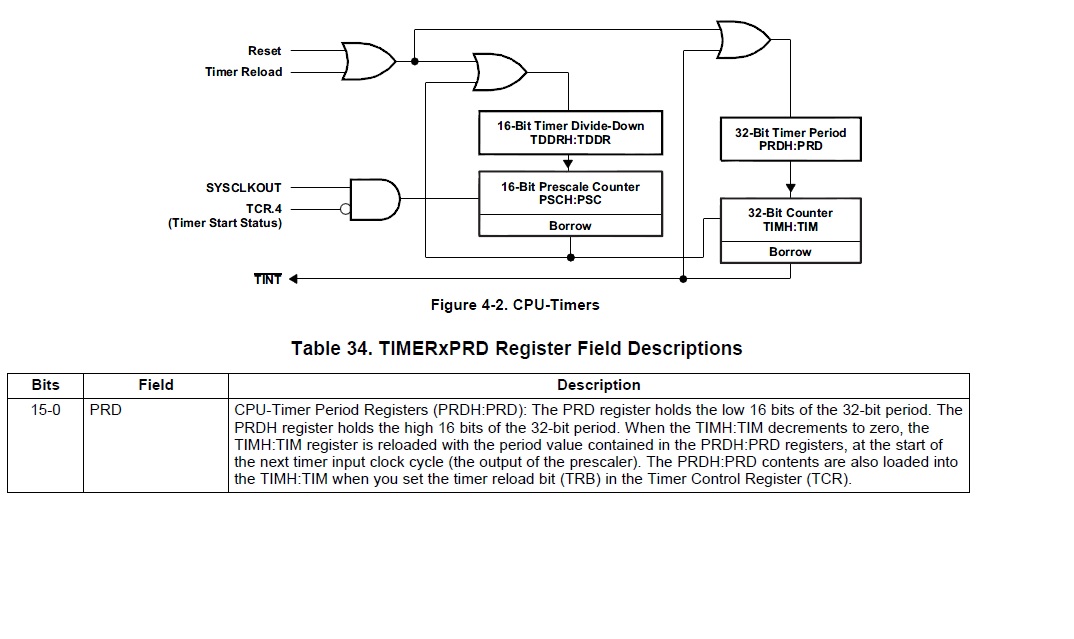
Here,I am not clear about timer period and system clock settings.How do we set the TPRD and its formula?
please answer the querry.Your help would be appreciated.
Thanks
Sneha Thakur