This thread has been locked.

If you have a related question, please click the "Ask a related question" button in the top right corner. The newly created question will be automatically linked to this question.

Virgin MSP430F5529 Failing to Program [URGENT]

Other Parts Discussed in Thread: MSP430F5529, MSP-EXP430F5529LP, MSP430F5528

Hi,

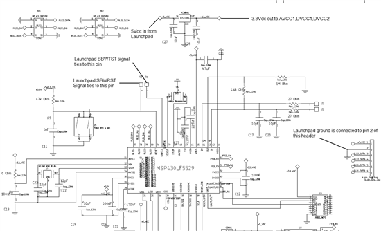
I am trying to program a virgin MSP430F5529 on a custom PCB that I made, but I am having trouble programming using the SBW interface from the MSP430F5529 Launchpad. I read the user's guide for the launchpad and it states that you can program an external target using the LP SBW pins. I am supplying AVCC1 and DVCC, I also have a 47k pullup and 1nF on the reset line. Any insight will greatly help as this is for my final project.4784.LV_SCHEM.pdf

  • Hi Omar,

    It will probably help if you can show what specific pins on the F5529 Launchpad you have connected to what pins on your custom board so that people can double-check your connections. A picture of your setup or a diagram could help. Your schematic only showed that RST and TEST go to some jumper called J2, but not how you connected this to the 5529 launchpad. You also will have to connect Vcc and GND to the Launchpad.

    Regards,

    Katie

  • The pins that I am connecting from the launchpad to my custom application are the SBWTST, SBWRST, GND, 5V. I connect 5v and ground to the header on the far right of the schematic. The 5v signal goes to a 3.3Vdc regulator that supplies the MSP430 AVCC1,DVCC1,DVCC2 and all associated peripherals. The GND from the launchpad is also connected on that header, but it simply goes to the ground plane on the board. What are the minimum connections that the MSP430 needs to be programmed? I am new into PCB layout and I need to have this chip programmed before the end of the week. FYI I am not using the USB functionality in my application and was simply going based on the launchpad schematic. I will appreciate if a schematic is provided so that I can set that up in Mentor Graphics. Thanks to All.


  • The application that I am using this MSP is for a smart outlet application. The peripherals that are in use are USCIA and B, TimerA and B, and several GPIO. All other peripherals are not used. In essence, i only need the bare minimum requirements to power and program the MSP. I am pretty sure that I am overlooking the obvious, but I am a new to laying out my custom board with a virgin microcontroller. My code and peripherals work as expected when running them off the Launchpad and separate breadboards. The error that I keep getting when I plug in those signals is "Unknown Target Device" on the latest version of CCS

  • Hi Omar,

    Taking a closer look at your schematic, and since you mentioned that you aren't using USB on your custom board:

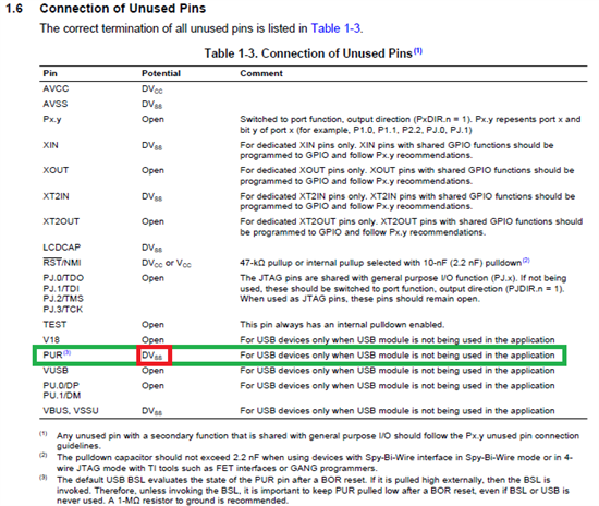
    There is a list of recommended connections for unused USB pins when you are not using the USB functionality on p. 68 of the 5xx User's Guide www.ti.com/lit/pdf/slau208. I would recommend pulling some of your passives off on these USB pins and using wires to make the USB connections match exactly what's listed in section 1.6. I'm wondering if your connections could be causing your MSP430 to start up in BSL mode from PUR being pulled high (see note 3 on the table I just mentioned) - you have some resistor network on it at the moment, but I'd recommend taking all that off and tying PUR to DVss. I would fix all of your V18, PUR, VUSB, DP, DM, VBUS and VSSU connections to exactly match those listed in the table and see if this helps - it will be best practice to correct this even if it turns out not to be root cause.

    Regards,

    Katie

  • I did remove those on my second revision of the board, but it still wont program. On the PUR line I connected a 1Mohm resistor, as suggested on the user guide. The msp still does not want to program using VCC, GND, SBWRST and SBWTST. Am I still doing something terribly wrong?
  • Hi Omar,

    Where does the user's guide recommend connecting PUR with a 1Mohm resistor - maybe you are looking at a different document?

    If you do not use USB, it is recommended to tie PUR to DVss, and also make sure that the other pins are all connected according to this table from p. 68 of the MSP430 F5xx/6xx user's guide: www.ti.com/lit/pdf/slau208

    Please follow these connections - some of the other USB pins needed to be changed too it looked like from your schematic. This is the way that we spec the device to work correctly when there is no USB hardware used on the board, for lowest power and correct operation, so we need to rule this out as an issue first.

    Regards,

    Katie


  • In the table above note (3) states that "It is important to keep PUR pulled low after a BOR reset, event if BSL or USB is never used. A 1-Mohm resistor to ground is recommended.

  • Hi Omar,

    Sorry about that I see it now - we were pointing at the same thing. So your 1MOhm resistor on PUR is pulling the pin to ground correct? Have you connected all the other USB pins to DVss or Open according to the table as well?

    -Katie

  • Hi Omar,

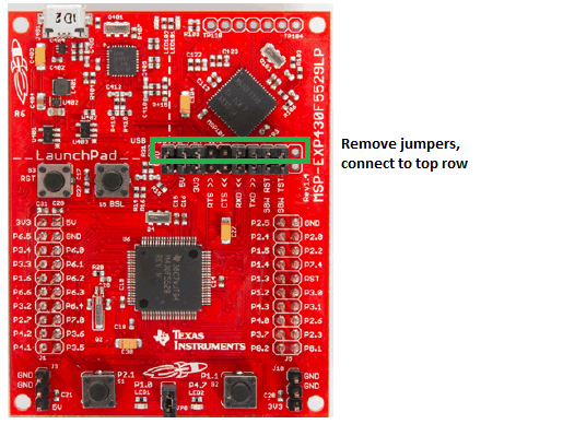
    I just thought of something - which side of the jumpers are you connecting to? You need to make sure if you are using the MSP-EXP430F5529LP Launchpad to debug another board, that after removing the jumpers on the programming header, you connect to the top pins (side closest to the emulation section and USB port) not the bottom pins (side closest to the F5529 on the board) - the bottom pins aren't connected to the debugging signals if the jumpers are removed.

    I did a test and tried this out on my own both ways. If I connect to the bottom pins, I get the same error as you (unknown device), but if I connect to the top pins from the header as shown in the picture below, it programs correctly.

    One other note - when I did my test I just connect the 3.3V jumper directly to my MSP430 Vcc (I don't have an LDO like you do on your board) - this could also be a test to make sure your LDO isn't somehow interfering with programming, to bypass the LDO and connect 3.3 directly to the MSP Vcc pin.

    Hope this helps,

    Katie


  • As you mentioned above, I am connecting to the row of headers closest to the emulator side; the ones highlighted in green. I did do all those changes in my layout and I am simply waiting for the board to get manufactured. I will post my results later today. On another note, is it a big problem if the LDO is not outputting exactly 3.3V? My LDO puts out like 3.27V.
  • Omar Vega said:
    On another note, is it a big problem if the LDO is not outputting exactly 3.3V? My LDO puts out like 3.27V.

    For just running the device, this should be fine. But for programming I am less sure - the problem is that the 5529 LP emulation does not have voltage sense capability (like the MSP-FET430UIF tool does) to be able to adjust its signals on RST and TEST according to what it sees on the board from an external supply. It is really only meant to be used where you are powering the board directly from the Launchpad so there's no voltage mismatch, rather than powering via an external source. See section 2.4 of the 5529 Launchpad user's guide www.ti.com/lit/pdf/slau533 where it says:

    "3. If the target voltage to be applied is anything other than exactly 3.3 V, remove the SBW and SBW TST jumpers. The emulator always runs at 3.3 V, and allowing the emulator to communicate with the target when their voltages are significantly different results in back-powering and possible unexpected behavior."

    "Notice that step 3 means that emulation is not possible if you are using an external power source at a voltage other than 3.3 V"

    So if you try and it still doesn't work with the LDO, I'd try to not power the LDO or somehow disconnect it, and tack on a wire just for supplying the voltage directly to the MSP430 while programming the part, such that you can power the MSP430 from the Launchpad 3V3 pin while programming, to rule out variables.

    Regards,

    Katie

  • The SBW signals from the LaunchPad are driven by GPIO pins of a MSP430F16xx chip. As such, both the signal strength and timing are very marginal. They normally work when used with the target on the same PCB an inch away. But when you connect them with wires or cable to another PCB, they might not work despite of being connected "correctly". Take a look of these signals at you target end with an oscilloscope. Can you see the rise/fall edges? How long do they take to reach the logic "1" or "0" level (if ever)?

    BTW, that MSP430F16xx on the LaunchPad is running at 12MHz and outside the specification (8MHz max.).

  • Hi old_cow_yellow,

    The MSP-EXP430F5529LP Launchpad actually has a new emulator called the "eZ-FET Lite" that uses an MSP430F5528 device instead of the F16xx you find on the G2xx Launchpad or previous eZ430 emulators - its firmware is also open source if you'd like to take a look. It has more capabilities too (like supporting all MSP430 devices and being capable of firmware updates, unlike the earlier eZ430 emulators).

    http://processors.wiki.ti.com/index.php/EZ-FET_lite

    Open source package: http://software-dl.ti.com/msp430/msp430_public_sw/mcu/msp430/MSP430_ezFETLite/latest/

    Your suggestion about checking the signals with an oscilloscope is a good one, as SBW can be pretty timing sensitive. I think that the mismatch in voltages could also cause an issue (different supply voltage between the target and the programmer is going to mean different thresholds so different timings, among other issues).

    -Katie

  • Thanks Katie and old_cow_yellow. I am still unable to program the microcontroller even after changing the schematic as you suggested earlier. I was able to program another msp430f5529 launchpad using an msp430f5529 launchpad without any problems. This was to simulate my scenario, but using 2 launchpads. On my pcb, i checked the voltages going into avcc and dvcc and both were at 3.275V. I tried programming and i got the unknown device pop up on ccs. I retried programming, but i now supplied the 3.3 from the launchpad, and i still had a problem. On the set line i have a 47k pullup and a 2.2nF pulldown. The TEST line is a straight pass-thru. Another thing i noticed was that VCoRE had 1.5V potential in the bypass cap. Is this normal?
  • It looks like you have the correct cap on Vcore, and it should be a lower voltage like that - it is the core voltage of the device which is set with an internal LDO in the PMM module that steps it down from the 3.3V coming in to the correct voltage for the current Vcore setting. Looking at the datasheet for the F5529 on p. 62 you can see the Vcore voltages for different settings, and 1.5V is in the correct range for the default core level (level 0).

    For the RESET pin, you could try disconnecting the 2.2nF completely - the cap is good to have for normal operation to prevent glitches on the RESET line, but added to the long lines that you are going to have from using wires to connect to the programmer maybe it could mess with the SBW signal timing.

    I think at this point you should definitely try old_cow_yellow's advice: try putting an oscilloscope on the TEST and RESET lines for your two setups (the two Launchpads vs the Launchpad and your board) and seeing if the signals look different when you try to program (slower rise/fall etc) with these different boards. You should also keep checking all the pin levels and connections like it sounds like you've begun to do, to find any incorrect connections or shorts. Do you have the schematic with the changes that you made?

    -Katie


  • I dont have the schematic with me. The only pictures i have at the moment are of the actual pcb layout. I will try this later today and will post the results.
  • Hello,

    I have a same problem.

    I want to program a different device(MSP430F5528). As mentioned in "2.5 Using the eZ-FET lite Emulator With a Different Target", I need to wire 4 signals(3.3V, GND, SBWTDIO and SBWTCK).

    The target device will be powered by a 3.3V power adapter. 3.3V from the emulator and 3.3V from the target device should be connected?  I think this will make a damage.

    The capacitor on the RST pin can not be greater than 2.2UF, any limit for the resistor on the RST pin? 

    Thank you

    Fei

  • Directly connecting the two may cause oscillations in the regulator circuits.
    However, the MSP can stand a difference of up to 0.2V between VCC and any input voltge. So it is sufficient if the two voltages are closer than 0.2V.


  • I have solved this problem. Just remove the reset capacitor. The MCU can work without this capacitor.

  • Fei Yan1 said:
    The capacitor on the RST pin can not be greater than 2.2UF,

    The suggested value is 2.2 nanofarads. That is three orders of magnitude less than 2.2 microfarads you mentioned you were using.

    I think you'll find that if you use the correct value, the circuit will work just fine, plus you will be following TI's design guidelines.

  • Fei Yan1 said:
    The capacitor on the RST pin can not be greater than 2.2UF

    Not the capacitor on the RST pin, but the total capacitance on the RST pin (or rather the SBW signal lines), including any line capacitance. And it's 2.2nF, not 2.2µF.
    Also, line length is an issue, as SBW uses bi-directional signals without a direction control signal. So long lines lead to reflections and signal direction mismatching. SBW is very fragile regarding signal conditioning and runtime.

**Attention** This is a public forum