This thread has been locked.

If you have a related question, please click the "Ask a related question" button in the top right corner. The newly created question will be automatically linked to this question.

MSP430 SPY Bi-Wire Programming issue

Other Parts Discussed in Thread: MSP430F2274

Hi,

I am using MSP430F2274 and trying to program it by spy Bi-wire interface. In datasheet it is mentioned that for programming Minimum voltage required 2.2V but my designed board is not getting programmed below 3V. Tested by 3V coin cell battery as well as dc regulated power supply.

In reference board, i am able to program below 3V but issue is coming in my designed board.

Could you help me what will be issue in my designed board?

  • Most common mistakes:

    • Forget putting a 47K pull-resistor on reset line.
    • Using a larger cap than 2.2nF on reset line.
    • A cable that is longer than 20cm.

  • Hi Tony,


    Thanks for feedback.

    1) Pull up resistor is there 33K.

    2) I am not using any cap on reset line as in reference board it is also not there.

    3) About which cable you are talking?

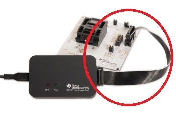
  • The one from the debugger/programmer to the processor

    Could also be a selfmade cable if you're using a LaunchPad for debugging/programming.

    TI recommends a 2n2 capacitor from RST to GND and a 47k resistor from RST to Vcc.

  • You don’t tell which tool you are using, assuming you are using the TI FET are you sure you are Sensing board Vcc and not Sourcing from FET?

    Your RST setup, single 33K resistor, is ok.


    Here are some general rules for a JTAG connection;

    JTAG connection 2-Wire, Vcc (sense) from target, MCU is powered by target board PS and not by JTAG:

    • Connect SBWTDIO (/RST) from MCU to JTAG TDO/TDI pin-1.

    • Verify the SBWTDIO (/RST) pull-up resistor is not smaller than 4.7KOhm and the (ground) capacitor not greater than 2.2nF. If any doubt remove both, the JTAG doesn’t (like/) need them.

    • If the Reset is provided from another source, be sure this is an ‘open-collector/drain’ type, is floating and from low capacitance.

    • Connect SBWTCK (/TEST) from MCU to JTAG TCK pin-7. A connection to JTAG pin-8 is normally not necessary and in this case the series resistor is not required.

    • Don’t use long connection cables (>150mm).

    • If using flat-cable use the outer conductors for SBWTDIO & SBWTCK, this reduces their capacitance by ½. Next to both wires Vcc or Vss for shielding.

    • Connect Vcc from MCU to JTAG VCC-TARGET pin-4.

    • Connect Vss from MCU to JTAG GND pin-9.

    • Do not make any other JTAG connection as the above 4 ones.

    When using CCS start with the ‘Slow’ speed option in the ‘Target Configuration’.


**Attention** This is a public forum