This thread has been locked.

If you have a related question, please click the "Ask a related question" button in the top right corner. The newly created question will be automatically linked to this question.

Power Meter Neutral Resister Offset

We are starting the UL phase of  our power meter project based on TI's EVM;
 http://www.ti.com/tool/evm430-f6779
UL is requiring us to use an impedance on all phases as well as the neutral phase for protection from the mains. We are using a 5 Meg high voltage resistor for this and replaced the EVM R5,R6,R7 resistors in the below schematic for each phase. We also changed the burden resistor for the same ratio. We can do this for all three phases and all is well. It calibrates great!
When we add in the required 5 Meg neutral resistor after the L6 in the schematic below (tidr376.pdf) this
gives us an offset into the V1-, V2-  and V3-.
My question is, Do you know a way in meter lib software to compensate for the neutral resister addition?
  • It sounds like your issues relate to UL rules, because I have not encountered similar questions from other parts of the world. I am trying to find someone familiar with UL certification, who can provide useful input on this. I will get back to you.

  • I have talked with some people who are more familiar with UL testing, and they do not recognise the issues you are facing. Why has it been necessary to increase the value of the voltage divider resistors? Did you compensate by increasing the lower resistors in these dividers, to bring the ADC signal level back to its original level? It would also be necessary to rebalance the anti-alias filter to minimise the phase shift it causes. If you don't do that the phase shift can be somewhat temperature dependent, due to the poor temperature coefficient of most reasonably priced capacitors. I do not understand what you are trying to achieve by putting a resistor in series with the neutral. Can you explain in more detail?
  • >When we add in the required 5 Meg neutral resistor after the L6 in the schematic below (tidr376.pdf) this gives us an offset into the V1-, V2-  and V3-.

    5Meg required in seriesi with neutral? Seriously?

    Do they (UL experts [?] ) care about environment such way ? - By adding 5Meg series resistor to neutral wire of all equipment so it simply does not work anymore :)

  • 1) We used high voltage resistors that were 5Meg as is common on other commercial meters such as Schneider Electric. These HV resisters will help

    us pass the UL over voltage test which is around 3100V peak.

    2) Yes, we did compensate as per the original post to keep the ratio the same. Do you have more info of how to rebalance the filter?

    3) For meters with user interfaces, UL requires 2 levels of protection to the user from the mains. One is provided by isolation on the 

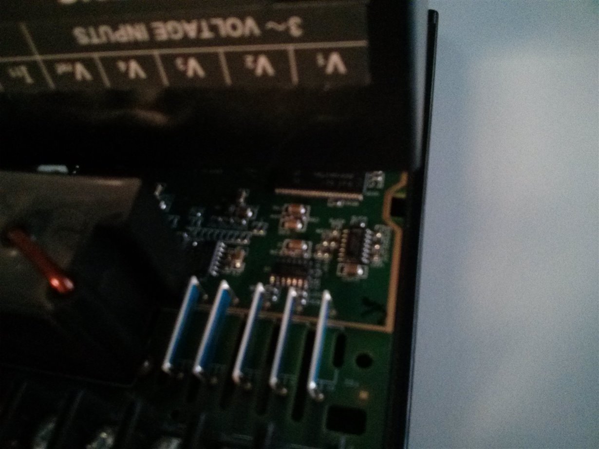
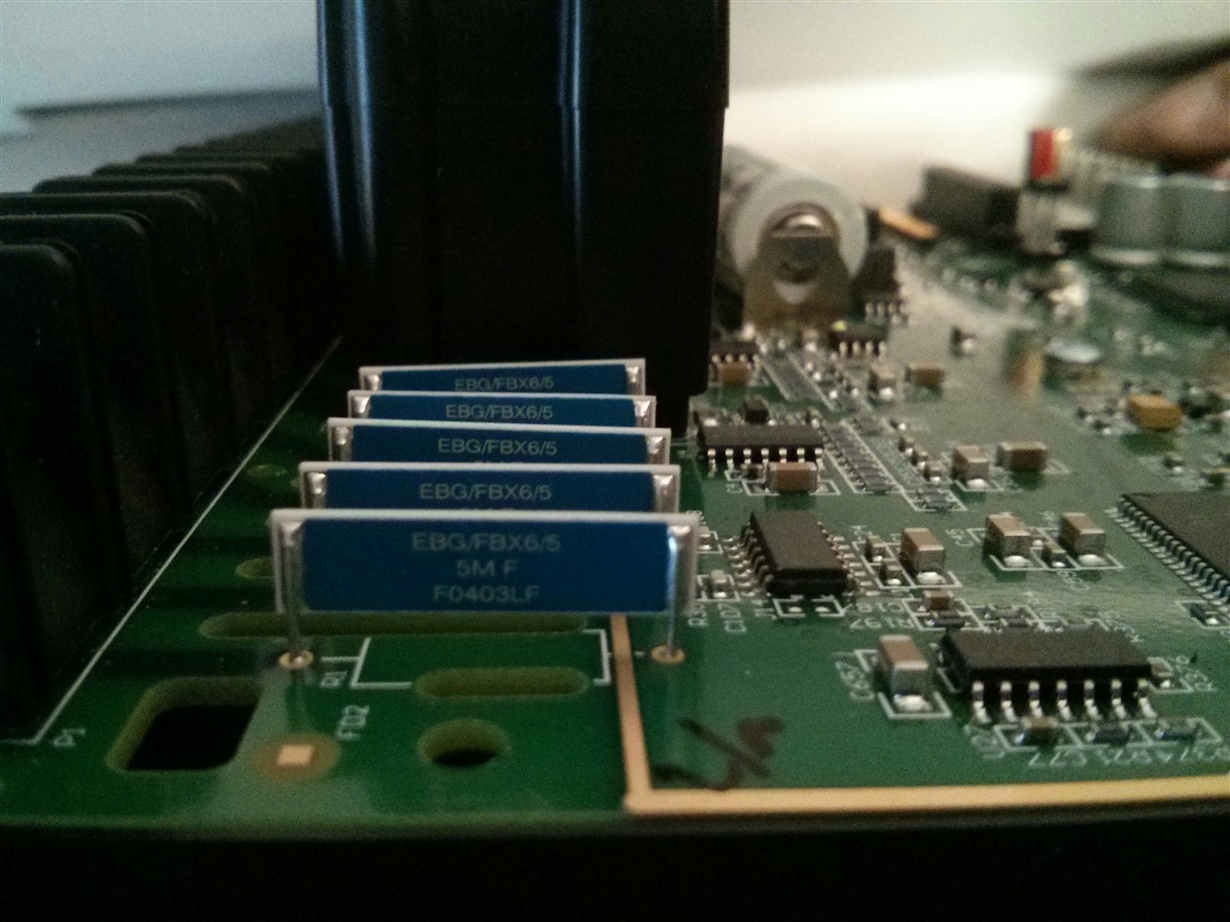
    user interfaces ie Ethernet, RS485. The other is to put "Impedance"  resistors before the burden resistor. If you were to open up a commercial meter such as the Schneider Electric 7650 meter you will see the resistors including the Neutral resistor on the Vref line. See attached pictures. Do you know how to compensate for the offset it creates?

  • The Schneider ION7650 is a panel mounted power quality meter. I don't know the details of this particular unit, but these typically have an electronics core powered by an isolated power supply, and high impedance paths to sense the three phase voltages, the neutral, and possibly the earth, with reference to the ground voltage of the electronics. I see 5 high voltage resistors in the picture of the 7650, so I assume it is measuring the earth voltage. I think it will be using 5 ADCs, concurrently sampling these 5 signals. The exact phase voltages can be worked out, by subtracting the neutral to electronics ground voltage from the 3 measured phase to electronics ground voltages.

    The TI EVM does not measure the the neutral to electronics ground voltage. It is build around the electronics ground being bonded to the neutral, so the three measured phase to electronics ground voltages are the same as the three phase to ground voltages. This is how most utility energy meters are built, including the UL approved ones for the US market which I have seen. If the 7th ADC of the MSP430 is not being used to measure the neutral current it could be used to measure the neutral to electronics ground voltage, and achieve the effect you are looking for.

  • Since each meter has to be calibrated. Your thoughts on the possibility using the A/D at calibration time and building cal tables one without the Neutral resistor and one with to compensate for the offset?
  • Skip Rye1 said:
    Since each meter has to be calibrated. Your thoughts on the possibility using the A/D at calibration time and building cal tables one without the Neutral resistor and one with to compensate for the offset?

    Don't you think that during calibration your meter shall be UL-approved too? I think your problem is that you are trying to approve your meter for class it is not designated to. Are you building utility meter or household appliance? Big difference there.

  • Look, Steve has already said that the spare A/D can be used. Please, if you are not answering the question, don't bother posting, Thank You. I'd like to hear Steve thoughts in regards to the calibration question.
  • >don't bother posting, Thank You.
    Well... sorry I wasted your precious time. I raised valid question btw: appliance or utility meter.

  • Hi Steve,

    Yes, we can use the A/D for the neutral current to measure the Neutral Voltage.

    Does the attached look reasonable to you?

    Your thoughts on how I need to go about updating the meter lib to compensate for the new voltage reading?

    GPT_P6_Meter_Simple_NonConfidential.pdf

  • You schematic won't work. You have created potential dividers for the voltage ADC inputs which will result in high enough voltages at those inputs to damage the IC.

    You need 4 separate voltage dividers from the 3 phases and neutral, down to the Vss line of the IC. With a divider tap connected to the positive input of an ADC, through an anti-alias filter, and Vss connected to the negative input through an anti-alias filter, the voltages at the ADC inputs will always be within spec. Voltage surge conditions on the power lines are an exception to this. You will need to provide protection circuitry to avoid damage under such surge conditions.

    Once you have 4 line-to-Vss voltages you can work out the the star voltages, or the phase to phase voltages, by simple subtraction. The star voltages will be differences between the three phase samples and the neutral sample. The three phase-to-phase voltages will be three differences between phase samples. Of course, the samples will need to be time coincident for this to work well, so the delay feature of the sigma-delta converters should not be used in the voltage channels, and the external analogue filters will need to be designed to cause a very similar phase shift in all 4 channels.

  • OK, I will build the necessary hardware referenced to Vss.

    Would the simple subtraction occur right before the DC compensation call?

**Attention** This is a public forum