This thread has been locked.

If you have a related question, please click the "Ask a related question" button in the top right corner. The newly created question will be automatically linked to this question.

MSP430G2422 power down with slow slope

Other Parts Discussed in Thread: MSP430G2433

Hi Champs,

My customer is using MSP430G2433 in their products. When they were taking voltage drop test, they found the behavior of MCU was abnormal. The AC input voltage(220VAC) would disappear for 1.5s, then 3.3V and 5V will be power down, then power up again. 

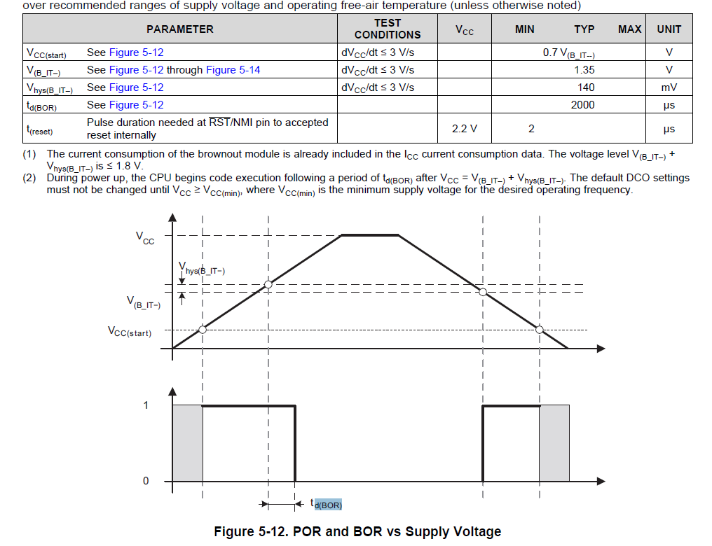
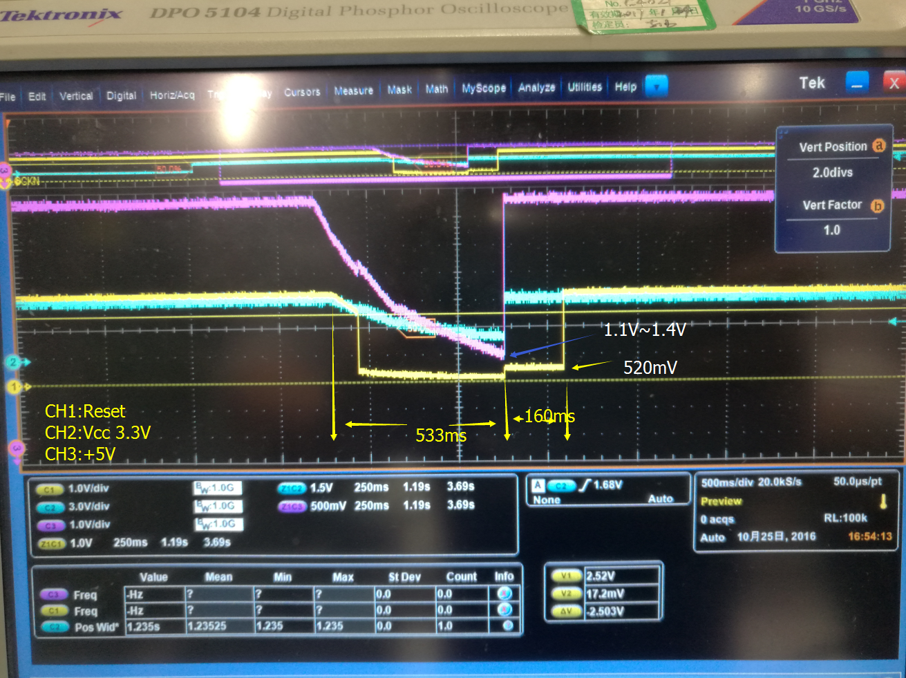
MSP430G2433 with 12MHz(2.5V Vcc at least) MCLK, SPI master was used. ACLK, MCLK, SMCLK were driven by internal clock source. When taking voltage drop test, +3.3V would drop to 1.1V~1.4V with 533ms, then repower up again. From chapter 5.11(BOR/POR) of datasheet, we can know V(B_IT–) =1.35V, which is very close to the lowest Vcc level. We have several questions as follows:

1. From the scope capture we can know RST would be pulled down when Vcc was 2.5V. From datasheet V(B_IT–) =1.35V, looks this value cannot follow the datasheet. Can you help to check this?

2. What would be happened, when MCU was set to 12MHz with lower power supply, which is less than 2.5V?

3. When re-power up again, the lowest voltage level of RST is about 520mV, not zero. Is there any internal resistor on RST internally?

4. The duration time of RST after power up is about 160ms, and from datasheet, td(BOR) is about 2ms. Why this condition happened?

Thanks a lot.

Regards,

Young

  • Hi Young,

    1. As you can see in Figure 5.1 of the Datasheet, minimum operating supply voltage depends on the system frequency. The device can no longer operate at 12 MHz under 2.7 V, therefore the device enters a reset condition. The minimum operating Vcc is different from V(B_IT–), the voltage at which the device is released from the BOR. The default DCO settings must not be changed until VCC ≥ VCC(min), where VCC(min) is the minimum supply voltage for the desired operating frequency.
    2. The MCU is not allowed to operate under 2.7 V at 12 MHz.
    3. The MSP has an internal RC delay that holds the MSP in reset state for a certain time after the brownout circuit has detected the presence of VCC.
    4. I'm not quite sure what is causing this behavior, is it the same for a normal power-on condition?

    Regards,
    Ryan
  • Young Hu said:
    1. From the scope capture we can know RST would be pulled down when Vcc was 2.5V. From datasheet V(B_IT–) =1.35V, looks this value cannot follow the datasheet. Can you help to check this?

    Only explanation I see here - CPU crash which in result leads to Watchdog reset (if used). I would suggest to use external supply voltage supervisor having proper treshold voltage for 12MHz. Other option for such a slow VCC drop would be continuous VCC monitoring using ADC which changes DCO freq to "safe" 1MHz when voltage becomes too low for hi-freq operation.

  • Hi Ryan/Ilmars,

    Today customer sent his schematic to me. They have supervisory circuit on their board....An APX809 is used to monitor the power supply of Vcc. The supervisory circuit is as follows. The reset active timeout is about 140ms~280ms, which is matching with scope capture. And also the 520mV voltage level comes from the resistance divider, 3.3V*10K/(10K+47K) = 530mV.

    Thanks a lot.

    Regards,

    YOung

  • Divider between supervisor logic ouptut and RST logic input of uC is really bad idea. R882 shall be removed and R883 shall be 0 ohm, not 40k. Supervisor shall be APX809/810-29 because >= 2.7V is needed for 12MHz

  • Hi Young,

    Please advise the customer with Ilmars' comments, which are all valid for this case.

    Regards,
    Ryan

**Attention** This is a public forum