This thread has been locked.

If you have a related question, please click the "Ask a related question" button in the top right corner. The newly created question will be automatically linked to this question.

CCS/MSP432P401R: Problems with 12+ MHz DCO frequencies

Part Number: MSP432P401R

Tool/software: Code Composer Studio

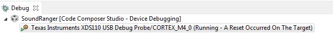
I am attempting to get the DCO to clock to it's maximum frequency of 48 MHz.  However, if I use anything above 12 MHz, the debugger will begin to continually reset itself.  At this point, if I try to load new code, CCS will say that the board is no longer a MSP432P401R and I have to factory reset it.  Does anyone know of problems that might make this arise?  Pictures and test code below.  Thanks for the help.

//*****************************************************************************
//
// MSP432 main.c template - Empty main
//
//****************************************************************************

#include "msp.h"
#include "driverlib.h"

void main(void)
{
	
    WDTCTL = WDTPW | WDTHOLD;           // Stop watchdog timer

    CS->KEY = 0x695A;
    CS->CTL0 |= 0x40000;
    CS->KEY = 0x0000;
    int n=0;
    while(1)
    {n++;}
	
}


  • void clockInit(void)
    {
        /* 2 flash wait states, VCORE = 1, running off DC-DC, 48 MHz */
        FlashCtl_setWaitState( FLASH_BANK0, 2);
        FlashCtl_setWaitState( FLASH_BANK1, 2);
        PCM_setPowerState( PCM_AM_DCDC_VCORE1 );
        CS_setDCOCenteredFrequency( CS_DCO_FREQUENCY_48 );
        CS_setDCOFrequency(48000000);
        CS_initClockSignal(CS_MCLK, CS_DCOCLK_SELECT, 1);
        CS_initClockSignal(CS_SMCLK, CS_DCOCLK_SELECT, 1);
        CS_initClockSignal(CS_HSMCLK, CS_DCOCLK_SELECT, 1);
    
        return;
    }
    

    Is this your board or the Launchpad? If your board, what crystal frequency?

    My Launchpad works fine with the grlib 5300 touch screen example with the above. I did remove the CS_setDCOFrequency(48000000); line since it appeared redundant.

  • This is using the Launchpad. I've added the 2 wait states to the test code and it seems to be working now. Can you go into any detail as to what the wait states are and why they are needed?
  • Not really, I just followed the example. 8^). But it seems that the flash memory is too slow to keep up at 48 MHz, so you need to tell the CPU to delay a bit to get valid reads.

    From the 432 family users guide:
    "The Flash Controller is configurable in terms of the number of memory bus cycles it takes to service any
    read command. This allows the CPU execution frequency to be higher than the maximum read frequency
    supported by the Flash Memory. If the bus clock speed is higher than the native frequency of the Flash,
    the access is stalled for the configured number of wait states, allowing data from the Flash to be accessed
    reliably.
    User software is required to program the number of wait-states into these registers based on the CPU’s
    execution frequency.
    MSP432 Driver Library APIs in Table 8-1 can be used to set the Flash wait state."
  • That makes sense. Thank you for the help.

**Attention** This is a public forum