This thread has been locked.

If you have a related question, please click the "Ask a related question" button in the top right corner. The newly created question will be automatically linked to this question.

MSP430F47187: Clamp diodes on terminals?

Other Parts Discussed in Thread: MSP430F47187

Hi,

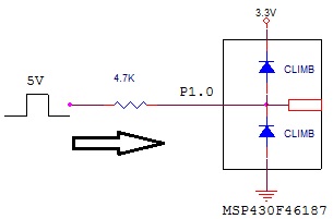
I have some 5V signals to enter MSP430 works at 3.3V. I dont want to use level translator or divider. If MSP430F47187 has internal protection diodes on its terminals, I think I can use them with only a series resistor. But I couldn't find any information about these propection diodes in the datasheet such as what is the current rating, which terminals have these protection.


10x,

BP.

  • MSP430 internal ESD protection diodes have an absolute rating of +/- 2 mA. And in this particular case, where the max difference between the supplies (VCC of the MSP430 and I/O drive) is 0.3V (assuming this includes the worst case tolerance of the supplies), a small series R should be fine. In this case the series impdedance should be greater than 0.3V/2mA =150ohms.

    None of the absolute max ratings must be exceeded. A current within the limits is one thing but at the same time the voltage must not exceed the - 0.3V.. 0.3V+DVcc . Exceeding one of the limits might affect the quality/function of the product.

  • Hi,

     So, (5V - 3.3V - 0.3V) / 4.7Kohm = 0.3mA, this circuit should be OK right?


    Thanks.

  • The current spec is fine (since its within 2 mA), but the voltage spec on the pin is violated here (> 0.3V +DVCC)

  • Hi Harman,


    Are you sure? Because in that case, P1.0 voltage never will exceed Vdd+Vdiode which is Vdd+0.3V because of series resistor.


    Thanks,

    BP.


  • Harman said:
    The current spec is fine (since its within 2 mA), but the voltage spec on the pin is violated here (> 0.3V +DVCC)

    This is a hen-and-egg situation.

    The maximum voltage is VCC+0.3V, as any higher voltage would raise the diode current to near-unlimited amounts. If you keep the current below 2mA, the voltage will never raise above VCC+0.3V while if you keep the voltage below the limit, the current will never raise.

    If you select a series resistor that will cause a voltage drop of the excess voltage (1.4V) on a current of 2mA, neither current nor voltage will be off-limit.

    But this is a miscalculation anyway. The normal input current of the pins is usually some magnitudes smaller. It only starts to raise when the voltage limit is already almost met.
    So using an 700Ohm resistor will swallow 1.4V  at the maximum current of 2mA, yet using a 17kOhm resistor will do so for 100microamperes, which is still enough for the input.

    While the absolute minimum series resistor is 700Ohm, you can as well use 15k or 20k and it will still work fine.

    Another thing to consider is where the current flows. Sure, 2mA per pin will only cause 0.6mW heating power, but these 2mA will flow somewhere. They will flow into VCC.
    Now VCC is usually generated by a voltage regulator. And these regulators can only limit the amount of current flowing in from the supply voltage. The best they can do is to cut the current flow from teh supply voltage completely, but they cannot sink any current from teh output if it should become higher than the desired oputput voltage.
    Yet this is what happens when current flows through the diodes. If the circuitry sourced from VCC does not consume at least the current that flows to VCC through the diodes, VCC starts to raise, until inrush and consumption are equal. This can easily exceed the maximum VCC and (not so easily) destroy the MSP.
    An exception to this is when your voltage regulator is an OpAmp type, as these can source AND sink the output. But this is a rare case, because this kind of regulation is expensive for higher currents and also drastically reduces efficiency.

    p.s.: these diodes are CLAMP diodes because they clamp the input voltage between VCC and GND (+ diode voltage).

  • BasePointer said:
    I think I can use them with only a series resistor.

    A better way (if you're using digital signals) is  a antiseries diode and a pullup resistor. It will allow the external circuitry to pull the pin down, and if it is not pulled down through the diode, it is pulled up to VCC (an dnot more) by the resistor.
    Make the resistor as high as possible to limit the current consumption if it is pulled low. Also, a low shortcut current will keep the voltage drop through the diode low and also allow the signal source to swing nearer to ground (the higher the current, the higher the low-voltage). Both together may not exceed the low voltage level threshold of the input pins.

    Carefully selected values keep the overall current consumption low and prevent the voltage-raise poblem outlined in my previous post. At the expense of an additional diode.

  • I used to really enjoy finding clever ways to translate between voltages using only passives, but now I'm old and lazy.  Every manufacturer has a hundred different parts that do this for a couple pennies.  Here's one from TI in a 4-BGA (which is an awesome looking package that I've never had the pleasure of using...  < 1mm^2!!)

    http://focus.ti.com/docs/prod/folders/print/sn74lvc1g07.html


    -memoryleak

  • memoryleak said:
    Here's one from TI in a 4-BGA

    BGAs are difficult to solder manually. I prefer the SOT-23 package.

    The SN74lvcg07 sure is a nice baby. And it might be useful if you have problems with the low level voltage. Yet it isn't a common part and difficult to get if you only need one or two. Also, TTL series (especially 47HCT) offers some chips with multiple divers which do the very same (excepf tfor the ESD protection.

    Nicer are the ones with two supply voltages. But all this adds to PCB space and material costs. And if you produce more than one PCB (from ~20 up), PCB space and material costs ar eno longer a don't care. A simple diode with pullup, or a series resistor ( < 0.4 cents/resistor ) then is the better choice.

    Of course there are occurrences where you NEED some more special things. Our energy meter requires isolation between high-voltage and low-voltage part. Since the ADE we're using for measurement requires to be on the high-voltage side, we decided to route the SPI connection to the MSP through an ADUM chip, which offers 2000V isolation and operates on two separated (and isolated, of course) supply voltages, even mixed levels. This series has up to 6 modulated transformers in various combinations of input and output (or left and right or whatever) lines. Expensive, but better and much smaller than using optocouplers for either the SPI-to MSP or MSP-I/O side. It solves the isolationas well as the different voltages (3.6V MSP and 5V ADE)


**Attention** This is a public forum