This thread has been locked.

If you have a related question, please click the "Ask a related question" button in the top right corner. The newly created question will be automatically linked to this question.

RTOS/MSP430FR5994: Problems receiving data from the SIM800 GPRS module

Part Number: MSP430FR5994
Other Parts Discussed in Thread: MSP-EXP430FR5994

Tool/software: TI-RTOS

Hello,

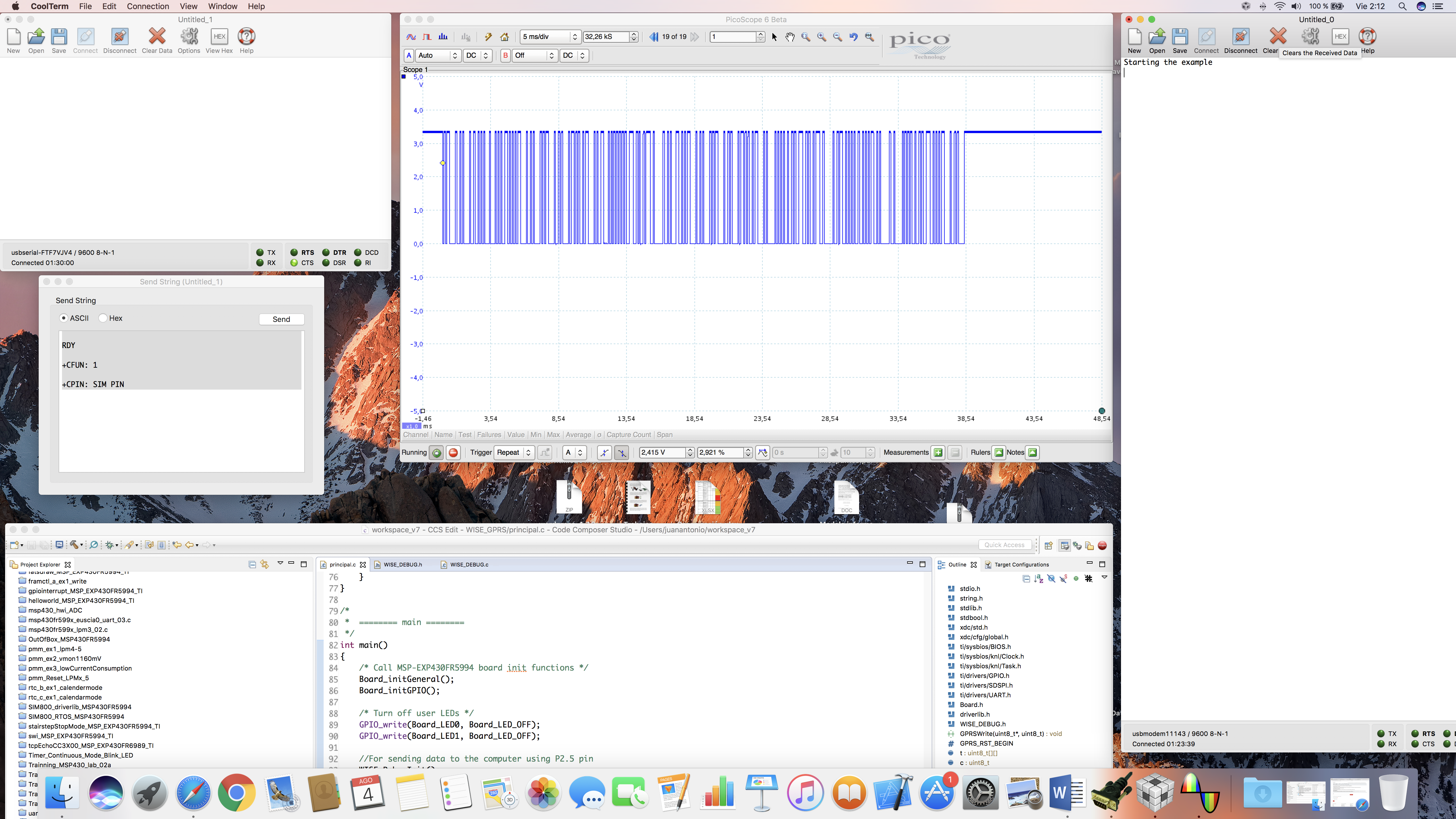
If I reset the SIM800 module I should get three responses.

RDY

+CFUN: 1

+CPIN: SIM PIN

The responses always start and end with the same sequence: \r\n or 13 10

I wrote a program using DriverLib which reset the module every 10 seconds, wait the 3 responses using EUSCI_A0 and sends the responses to the computer by using EUSCI_A3. This example is attached and works perfect.

However, I am trying to do the same with RTOS and it works well less times and the rest I receive wrong characters.

This is the output of the DriverLib example:


RDY

+CFUN: 1

+CPIN: SIM PIN

RDY

+CFUN: 1

+CPIN: SIM PIN

RDY

+CFUN: 1

+CPIN: SIM PIN

RDY

+CFUN: 1

+CPIN: SIM PIN

RDY

+CFUN: 1

+CPIN: SIM PIN

RDY

+CFUN: 1

+CPIN: SIM PIN

RDY

+CFUN: 1

+CPIN: SIM PIN

RDY

+CFUN: 1

+CPIN: SIM PIN

And this is the output with RTOS:


RDY

+CFUN: 1

+CPIN: SIM PIN
*

RDY

+CFUN: 1

+CPIN: SIM PIN

RDY

+CFUN: 1

+CPIN: SIM PIN
*

RDY

+CFUN: 1

+CPIN: SIM PIN
HVHh.U9 1
°•M%5PIN
*
HVHh.U9 1
°•M%5PIN

RDY

+CFUN: 1
°•N: SIM PIN
*

RDY

+CFUN: 1
°•N: SIM PIN

The UART has the same configuration is both examples.

I hope that you can help me with this issue because I am testing it many days.

Thanks and regards,

Juan Antonio

SIM800_driverlib_MSP430FR5994.zipSIM800_RTOS_MSP430FR5994.zip 

  • Hi Juan,

    It seems like the Baud rate has some problem between MSP and computer, could you check the Baud rate setting and measure the wave with oscilloscope?

    regards
    KC
  • Hello,

    I will check the wave with the oscilloscope, but the problem is that the EUSCIA0 is measuring wrong characters in the Rx line (P2.1). I know this because my previous program was based on receiving the frames and comparing them with the expected response and less times the code worked well. Moreover, I had the Tx line of the GPRS connected with the Rx line (P2.1) and with an USB to serial converter. With this configuration, I could see good responses with a terminal program on the computer and errors receiving with the MSP430 UART.

    Thanks and regards,

    Juan Antonio
  • I have observed that the project always works well when I am not debugging it. However, I get many wrong bytes when I am debugging the project. This is the programa sequence:

    Void taskFxn()
    {
    static uint8_t gprsStatus = GPRS_RST_BEGIN;

    while(1)
    {
    Semaphore_pend(LogDataSem, 10000);

    switch(gprsStatus){
    case GPRS_RST_BEGIN:
    indexgprs = n = anterior = 0;
    memset(bytes, 0, 60);

    System_printf("Init GPRS\n");
    System_printf("RST begin\n");
    System_flush();

    //Reset the GPRS module
    //EUSCI_A_UART_disableInterrupt(EUSCI_A0_BASE, EUSCI_A_UART_RECEIVE_INTERRUPT); // Enable interrupt
    GPIO_setOutputLowOnPin ( GPIO_PORT_P4, GPIO_PIN7 );
    Semaphore_pend(LogDataSem, 200);
    GPIO_setOutputHighOnPin ( GPIO_PORT_P4, GPIO_PIN7 );
    //Semaphore_pend(LogDataSem, BIOS_WAIT_FOREVER);
    Semaphore_pend(LogDataSem, 5000);

    //System_printf("3 responses received\n");
    //RDY
    //+CFUN: 1
    //+CPIN: SIM PIN
    System_printf("Timeout ends\n");
    System_flush();

    //I write a separator character in the terminal
    EUSCI_A_UART_transmitData(EUSCI_A3_BASE, '*');
    EUSCI_A_UART_transmitData(EUSCI_A3_BASE, '\r');
    EUSCI_A_UART_transmitData(EUSCI_A3_BASE, '\n');

    //Printing the response
    uint8_t i;
    for(i=0;i<indexgprs;i++){
    EUSCI_A_UART_transmitData(EUSCI_A3_BASE, bytes[i]);
    }
    while(EUSCI_A_UART_queryStatusFlags(EUSCI_A3_BASE, EUSCI_A_UART_BUSY));

    indexgprs = n = anterior = 0;
    memset(bytes, 0, 60);
    break;
    }
    }
    }

    void GPRS_ISR()
    {
    uint8_t caracter;
    uint16_t isrStatus = EUSCI_A_UART_getInterruptStatus(EUSCI_A0_BASE, EUSCI_A_UART_RECEIVE_INTERRUPT);
    EUSCI_A_UART_clearInterrupt(EUSCI_A0_BASE, EUSCI_A_UART_RECEIVE_INTERRUPT);

    if(isrStatus & EUSCI_A_UART_RECEIVE_INTERRUPT){
    caracter = EUSCI_A_UART_receiveData(EUSCI_A0_BASE);
    //Echo the received character to the computer
    EUSCI_A_UART_transmitData(EUSCI_A3_BASE, caracter);
    bytes[indexgprs] = caracter;
    indexgprs++;
    }
    }

    As you can see I am not using the sentences System_print and System_flush while the GPRS module is sending bytes which are followed after a reset in the corresponding pin.

    Any idea why the UART reads wrong bytes while debugging?

    Thanks and regards,

    Juan Antonio
  • Hi Juan,

    Seems you are close to the root cause. :) when you say debugging, could you describe more detail like where did you set the breakpoint? For step run , the UART communication possible interrupted after few bytes received, for example, stopped in timer interrupt.

    The code sending byte to UARTA3 in UARTA0 ISR, suggest set a flag in UARTA0 ISA only and operate UARTA3 out of UARTA0 ISR.

    regards
    KC
  • Hello KC,

    I have the problem without set any breakpoint in the code. I have commented the sentence for sending the received byte in EUSCIA0 ISR and the problem persists.

    Thanks and regards,

    Juan Antonio
  • Hello,

    I can not solve the problem.

    Is there any minimum configuration in the .cfg file necessary for debugging the program??

    I attach a screenshot of the modules used in my project.

    Thanks and regards,

    Juan Antonio

  • Hi Juan,

    A couple things:
    1. The System_flush causes the System_printf data to go to the CIO buffer which is read by CCS. To read the CIO buffer, CCS actually stops the target, reads the CIO buffer and resumes the target. This can cause real-time impact. Can you try the TI-RTOS application without the System_flush. You can look at the data via Tools->ROV->SysMin->OutputBuffer . You'll need to halt the target to read this though.

    2. Why aren't you just using the UART driver in TI-RTOS. It would simplify your code.

    Todd
  • Hello Todd,

    I am not calling System_printf and System_flush while the micro controller is receiving data from the UART. I understand that in this case it should not be a problem. However, I will use the ROV tool in the future steps. Thanks for your recommendation. I use this tool since I followed the RTOS training videos.

    I am awaiting responses that begins and ends with /r/n. It is simple for me to use an ISR and testing if the previous characters is /r and the actual character is /n and stores the response in a ring buffer.

    As I know, with the UART drive I can read a specific number of bytes. Could you recommend me a general structure for solve this problem by using the UART driver?

    Thanks and regards,

    Juan Antonio.
  • Hello,

    I can not solve this problem yet after testing many things these days. I hope that you can help me.

    I wrote a simple function for sending frames to the computer using EUSCI_A1. Then, I can do this:

    WISE_DebugString("Error init UART for GPRS\n");

    And  I can see the outputs of my project on the computer.

    I am using a terminal on the computer for simulating the GPRS.

    Hardware configuration 1:

    I am using this typical converter: www.alibaba.com/.../FTDI-TTL-232R-3V3-USB-TTL_60565269561.html

    Remove the TxD jumper on J101 connector

    A wire between P2.5 (EUSCI_A1 Tx) and TxD jumper (on the FET side and close to the J101 text) is needed. This is for printing strings to the computer using the mentioned function.

    Connect the GND line of the USB-serial converter with the GND board

    Remove the RxD jumper on J101 connector.

    Connect the Tx line of the USB-serial converter with P2.1 (RxD jumper close to the >> text). I also have the oscilloscope connected on this line.

    Software configuration 1:

    Open two terminals on the computer configured at 9600 bps. One is used for simulating the GPRS module and it is associated with the USB-serial converter emulated port on the computer. The other one is used for listening the WISE_DebugString calls and it is associated with the emulated port on the computer of the MSP-EXP430FR5994 board.

    You could see on the right terminal (attached with emulated port of the MSP board) the beginning message. As soon as you see the string "TRYING", please send the 3 simulated responses of the GPRS module by using the other terminal (in my case on the left side of the screen):

    \r\nRDY\r\n

    \r\n+CFUN: 1\r\n

    \r\n+CPIN: SIM PIN\r\n

    You should see the 3 responses on the right termina 5 seconds after since the task has a pend call of 5 s. This is the output:

    As you can see on the screenshot I am not debugging the project with CCS and the project works as expected. It could be tested many times without any error. However this is the log when the play button is pressed (no breakpoints as set):

    1st ok, 2nd ok, 3rd only 2 responses are received, 5th no responses, etc.

    Of course the project could be tested without using the extra USB converter and only one terminal.

    Hardware and softare configuration 2

    Remove the TxD jumper on J101 connector

    A wire between P2.5 (EUSCI_A1 Tx) and TxD jumper (on the FET side and close to the J101 text) is needed. This is for printing strings to the computer using the mentioned function.

    Place the RxD jumper and connect the oscilloscope on this jumper. I am using two wires as jumper and an extra wire connected with the oscilloscope. 

    Open a terminal on the computer configured at 9600 bps. It is used for both, simulating the GPRS module and listening the WISE_DebugString calls and it is associated with the emulated port on the computer of the MSP-EXP430FR5994 board.

    The idea is the same: Waiting for the "TRYING message", sending the 3 responses of the simulated GPRS and waiting 5 seconds to see the responses received by the MSP430FR5994.

    In no debug mode it works without errors. However, it could be observed that the oscilloscope signal is longer than expected: 1/9600*10bits*37 bytes (the 3 responses) = 38,54 ms and it has 40 ms.

    And this is the output in debug mode:

    As you can see it also works on debug mode (again only play button, no breakpoints), but the oscilloscope signal is very estrange.

    If I press pause debug and send the frames, this is the oscilloscope capture. There are errors on the terminal because I am not press the send button many times after receiving the TRYING message.

    Finally, this is a screenshot on debug mode with the real GPRS connected with many error receiving the characters. The oscilloscope shows only the last response: \r\n+CPIN: SIM PIN\r\n

    And in no debug mode the projects works without any error. Again the oscilloscope shows the last response.

    And this is the project:

    WISE_GPRS.zip

    Thanks so much and regards,

    Juan Antonio

  • Hi there Juan,

    It might seems obvious but have you tried disabling the Ultra Low Power Debug Mode?

    Just go to your project properties and disable it under Low Power mode settings: 

  • Thanks so much! Now it works.

    This option was checked in the project that I am using as template and in macOS is difficult to see this option since there are more options below and the scrollbar is hidden.

**Attention** This is a public forum