This thread has been locked.

If you have a related question, please click the "Ask a related question" button in the top right corner. The newly created question will be automatically linked to this question.

MSP430F6459: MSP430F6459 ACLK shutdown in LPM3 mode

Part Number: MSP430F6459
Other Parts Discussed in Thread: MSP-EXP430FR5994

Hi everyone,

In LPM3 mode, ACLK should still work. But the following code in MSP430F6459 tells it will shut down ACLK( source from XT1=32KHz).

Besides, if my PCBA connet with MSP-Fet430UIF, ACLK is fine(LPM3).

Need your help on this.

Thanks.

Best Regards,

SeaFesse

#include <msp430f6459.h>

void main(void)
{
    
    WDTCTL = WDTPW | WDTHOLD;                 // Stop WDT
    
    P1DIR |= BIT0;
    P1SEL |= BIT0;      //P1.0----ACLK output
    
    PJDIR |= BIT2;
    // PJSEL &=~BIT2;
    
    while(BAKCTL & LOCKBAK)                    // Unlock XT1 pins for operation
        BAKCTL &= ~(LOCKBAK);
    

    // Setup UCS
    UCSCTL3 |= SELREF__XT1CLK;                   // Set DCO FLL reference = XT1
    UCSCTL4 |= SELA__XT1CLK;                     // Set ACLK = XT1
    
    __bis_SR_register(SCG0);               // Disable the FLL control loop
    UCSCTL0 = 0x0000;                      // Set lowest possible DCOx, MODx
    UCSCTL1 = DCORSEL_5;                   // Select DCO range 16MHz operation
    UCSCTL2 = FLLD_1 | 243;                // Set DCO Multiplier for 8MHz
    // (N + 1) * FLLRef = Fdco
    // (243 + 1) * 32768 = 8MHz
    // Set FLL Div = fDCOCLK/2
    __bic_SR_register(SCG0);               // Enable the FLL control loop
    
    // Worst-case settling time for the DCO when the DCO range bits have been
    // changed is n x 32 x 32 x f_MCLK / f_FLL_reference. See UCS chapter in 5xx
    // UG for optimization.
    // 32 x 32 x 8 MHz / 32,768 Hz = 250000 = MCLK cycles for DCO to settle
    __delay_cycles(250000);
    
    // Loop until XT1, XT2 & DCO fault flag is cleared
    do
    {
        UCSCTL7 &= ~(XT2OFFG | XT1LFOFFG | DCOFFG);
        // Clear XT2,XT1,DCO fault flags
        SFRIFG1 &= ~OFIFG;                 // Clear fault flags
    } while (SFRIFG1 & OFIFG);             // Test oscillator fault flag


    while(1)
    {
        __bis_SR_register(LPM3_bits | GIE);       // Enter LPM0, interrupts enabled
        __no_operation();                         // For debugger
        
    }
    
}


  • Hi SeaFesse,

    Can you clarify the issue you're having, please? Are you saying that the code should be turning off ACLK when it is in LPM3, but it is still appearing when you connect the PCB to the MSP-Fet430UIF? You are correct that ACLK should still be available in LPM3.

    Thanks,
    Ryan
  • Hello Ryan,

    Ryan E Meredith said:
    Are you saying that the code should be turning off ACLK when it is in LPM3, but it is still appearing when you connect the PCB to the MSP-Fet430UIF?

    NO, I'm saying ACLK should be still working on LPM3 with or witout MSP-FET430UIF. However, the fact is ACLK can not output on P1.0 if my PCBA unconnect with MSP-FET430UIF.

    On the other hand, if MSP-FET430UIF connect with my PCBA , ACLK runs well. 

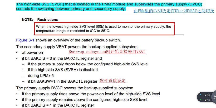
    BTW, I solved the problem today. The HW enginner leave pin VBAT unconnected. I go through the user guider on Battery Backup System Chapter, and found this pin should be connected with

    DVCC if Battery Backup System is not desired in the application.

    So, this issue turns to how MSP-FET430UIF makes these different. JTAG will affect the Battery Backup System? 

    Regards,

    Seafesse.

  • Hi SeaFesse,

    You are correct that VBAT should be connected to DVCC. I believe I replicated the behavior you are seeing using the MSP-TS430PZ100USB target board.

    It appears that when you plug in a cable that powers on the board initially (either through the USB or the JTAG connector) there is instability in the board supply voltage that causes DVCC to drop below the configured high-side SVS level. Since BAKDIS = 0 in the BAKCTL register, the supply powering the backup-supplied subsystem, which includes the XT1 oscillator, switches from DVCC to VBAT.

    When VBAT becomes the supply, it is connected to the capacitor on the VBAK pin which quickly discharges and the oscillator loses power, explaining why you did not see ACLK on P1.0. The following picture shows this behavior.

    After you connect the MCU to the debugger, the board is reset and DVCC is already stabilized, so XT1 remains powered by DVCC the entire time. This is why ACLK would remain visible on P1.0 despite the VBAT jumper being disconnected. The following picture shows when this happens. Since VBAT does not become the supply, it does not become connected to the capacitor on VBAK, and its value remains 0.

    Regards,

    Ryan

  • Hi Ryan,

    Really thanks for your time to replicate the issue.  I still have doubt and need your futher help.

    Ryan E Meredith said:
    It appears that when you plug in a cable that powers on the board initially (either through the USB or the JTAG connector) there is instability in the board supply voltage that causes DVCC to drop below the configured high-side SVS level. Since BAKDIS = 0 in the BAKCTL register, the supply powering the backup-supplied subsystem, which includes the XT1 oscillator, switches from DVCC to VBAT.

      I agree that the power on board initially is not quite stable.However,when I disconnect my PCBA from the UIF,  and then powered the PCBA by MSP-EXP430FR5994 , the power should finnally be stable after some time,that means the DVCC will rise above SVSH level , and the backup-supplier subsystem should switch to DVCC automaticly, and ACLK should recover running.Maybe it takes time, but 3 or 4 seconds is far enough, I believe. However, as we see,ACLK is still "dead".

    Besides, The code I pasted above , if I change LPM3 to LPM0, you'll find ACLK is always working regardless the state of VBAT or DVCC .If the cause is what you described above, it's hard to explain this.

    Regards,

    Seafesse.

  • Hi Seafesse,

    If you change the code you posted to include

        BAKCTL |= BAKDIS;

    after

        while(BAKCTL & LOCKBAK)                    // Unlock XT1 pins for operation
            BAKCTL &= ~(LOCKBAK);

    Then the ACLK signal should remain powered by DVCC and remain on regardless of entering lpm3 or the source used to power the board.

    Since your hardware setup and code did not initially follow the guidelines stated in the User's Guide, the behavior may not match what is specified in the User's Guide.

    Regards,

    Ryan

**Attention** This is a public forum