This thread has been locked.

If you have a related question, please click the "Ask a related question" button in the top right corner. The newly created question will be automatically linked to this question.

BQ25700A: Limit cycle in buck mode, does not boost

Part Number: BQ25700A
Other Parts Discussed in Thread: BQ4050

I am trying to use a BQ2700A as a boost battery charger.

Current target

  • 5V 3A (USB) -> 2S1P LiIon
  • 3u3 inductor @ 800 kHz
  • Using my own 4 layer board
  • Compensation networks copied (give or take capacitance tolerance) from EVM (I think)

(Note: in the future I may need higher input voltage, e.g. 12V 3A)

Here's what I have so far:

  • REGN at 6.06V, no major ripple
  • Some success talking with BQ4050 gas gauge chip for smart charging
  • Input 12V 350mA
  • Output 6.1V with ~12.5 Ohm load (approx. 500mA)
  • Temperature rise ~ 15 C at hottest component

The problem I'm having is that the charger only seems to operate in buck mode.

Do people have any thoughts??

I got the 'scope out, and I found that the PWM control seems to be really unstable. For 12V 250mA -> 6.1V ?? mA, I get the following waveforms on SW1 (yellow) and SW2 (green).  I am using very short probe connections to avoid noise pickup.  I would expect SW1 to be nice an periodic, and SW2 to usually sit at 6V with occasional dips to ground to recharge bootstrap capacitor 2.

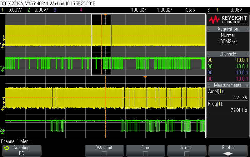
I checked that the switching frequency is correct and the switches aren't nasty/noisy (scope has 100MHz bandwidth), which is good.  However, SW1 and SW2 don't have waveforms like I would expect - I would expect SW2 be high almost all the time.

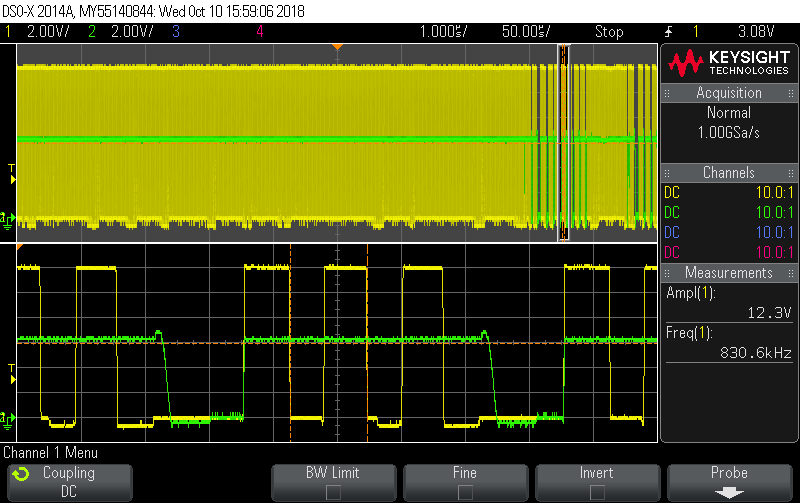
However, the charger won't boost.  Reducing the input to 5.1V, the Vsys sags to (i.e. out of regulation).  I'm not really sure what's going on here - SW1 and SW2 seem to be operating at different rates.  (Ch4 is the low side gate for SW2 node)

  • So I did some more investigating and made 2 changes:

    • I noticed that my schematic symbol had COMP1 and COMP2 swapped; the compensation network values were swapped.  I swapped them back.
    • I noticed that the input voltage had a heap of ripple.  I think this was causing oscillations with the fast current limit in my bench supply, so I added 1x 1000uF electrolytic to my existing 6x 10uF MLCC which helped a lot.

    Current situation

    • Boost mode now works OK when the input voltage is low enough.
    • Buck-boost mode sort of works, but has the limit cycle oscillations similar to above.
    • Buck mode sort of works, but has limit cycle osicllations similar to above.
    • The ADC current measurements are very jumpy.  I think this is due to the stability issue.
    • Charging with BQ4050 seems to work (haven't done detailed testing)

    Current questions:

    • I used a 3u3 inductor.  How sensitive are the compensation networks to inductance - should I just switch to the 2u2 inductor?
    • What R and C values should be used on the IADPT pin?  The EVK and datasheet don't agree.
    • The input current limit does make sense, however.  Does this indicate a problem?
  • Hey Jonathan,

    I am reviewing your question and will get back to you soon. I am reviewing the waveforms and test conditions you have captured.

    Regards,
    Joel H

  • Hello Jonathan,

    From your scope captures, the regulator appears to be entering PFM mode. During light loading conditions, the regulator will increase efficiency by entering PFM. During PFM there will be bursts of normal PWM pulses separated by an idle state in which both switch nodes are brought to ground. Your first and second scope captures appear consistent with this operation, especially the zoom in on the second.

    I verified on our EVM that with 12V input, I am seeing PFM operation until about 305 mA input current / 540 mA load current (at 6.144 V out, the default VSYS_min for 2 cell.) This is consistent with your test condition of 12V@250 mA.

    I believe that you will find that if you increase your load current, the PFM pulses will converge into a steady PWM stream. Likewise, if you reduce your load current, the PWM bursts will spread apart. If so, then this is expected operation for the device.

    Regards,
    Steve
  • Hello Steve

    This sounds reasonable.  Once I get a moment free at the office I will see about getting a variable DC load hooked up and try across a wide load range.

    Kind regards

    Jono

  • Hello again Steve

    I finally got some time for some more bench testing.  You are right - it's about the transition from pulse / burst mode to fixed frequency mode.

    For those who may be interested, I found the following transitions (with 3.3uH inductor, 800 kHz switching freq, 10mR sense resistors and battery charge disabled)

    Vin (V) Vsys (V)

    Transition to CCM

    (approx. mA)

    5 6.14 310
    5 8.44 220
    12 6.14 480
    12

    8.44

    880