This thread has been locked.

If you have a related question, please click the "Ask a related question" button in the top right corner. The newly created question will be automatically linked to this question.

BQ20Z95: bq20z95 - SN72PV195 Pin to Pin Replacement?

Part Number: BQ20Z95

Hello,

As it comes to my understanding SN72PV195 is replaced by bq20z95. I controlled the datasheets and saw two differences. COM pin (12) and CE pin (19) has changed to NC.

Since bq20z95 is almost a pin to pin replacement I tried to use it with my old circuit. But I'm having some troubles. LCD is not working anymore and current register (0x0a) always indicates 0 amps. When I draw some current from the circuit its value does not change. Hence OVP is not working.

Is there something that I need to considerate?

Thank you

  • Hi InProgress,

    Please check to see if your current sense resistor is populated. Use a volt meter to measure the voltage drop across the sense resistor.

    If the resistor is not an open circuit, please ensure the value is correct.... between 5 mohm to 20 mohm depending on your current level.

    the voltage drop across that resistor should be between +/- 0.25 V.

    Sincerely,
    Bryan Kahler

  • Thank you for the reply. We already checked the sense resistor. It's resistance and voltage range on it is correct

    When try to read the registers on a PCB with the old IC there is no problem, but when we try it with the bq20z95, we can not.
    As I mentioned before LCD is not working also.

    We do not believe that our circuit has a design problem we are using it for years. But the newer IC, bq20z95, may require some modifications.
    We are trying to understand that with your help

    Thank you in advance,
  • Hi InProgress,

    Please check to see if the gain of the ADC has been set to 0.

    If the value is proper, please send your gg.csv file and schematic for further analysis.

    Thank you!

    Sincerely,
    Bryan Kahler
  • We resolved the current issue with calibration.

    But we are still having trouble with the LCD. When we connect the circuit to bqstudio the 5-digit LCD bar graph we use, starts count 5 to 1 and repeats. It does not display the SoC of the pack as it should be. When we remove the SMBus connection all bars on the LCD are on, after around 10 seconds all of the bars start to fade and all gone. Can you help with that?

    Thank you,
  • Hi InProgress,

    I'm glad to hear that the issue with calibration has been resolved.

    With respect to the LCD bar graph tied to the LED output, please refer to section 2.5.2. Display Configuration and 2.5.3 Display format for the TRM.

    LED blink rate, flash rate, delay, hold time, and display format may be modified.

    Further debug would require the schematic, device configuration, and logs of the event.

    Sincerely,
    Bryan Kahler
  • Hello Bryan,

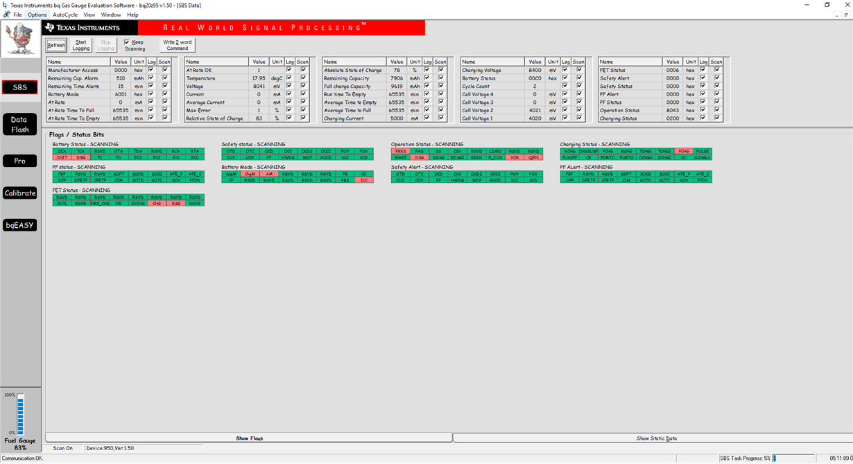
    Schematic of our circuit and status files that we are using with bq20z95 are in below. We checked LED blink rate, flash rate, delay, hold time and display format. We did not saw any problems. I've tried following Operation CfgA codes;

    0x0D21, 0xED01 and many others. And the display continued not to work. 

    And we also noticed that bq20z95 does not give any information about LCD support, but SN72PV195's datasheet were containing information about LCD support.

    Thank you,

  • The problem is continuing. Your help would be really appreciated.

    Thank you

  • Hi InProgress,

    Thank you for sending the schematic and view of your status registers. Please send a log of the event and the settings of your dataflash for further analysis.

    Thanks!


    Sincerely,
    Bryan Kahler