This thread has been locked.

If you have a related question, please click the "Ask a related question" button in the top right corner. The newly created question will be automatically linked to this question.

Just another post on bq51050b

Other Parts Discussed in Thread: BQ51050B

Hello,

I've some struggles with my bq51050b design.

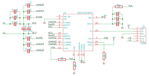
Here is my schematic diagram:

(Values of serial and parallel capacitors in receiver resonance circuit are only illustrative. Actual values were adjusted to the inductance of my RX coil.)

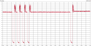
When I place the receiver over the transmitter pad, I get VRECT around 8 Volts. However, it is interrupted every about 10 seconds. Here is the waveform:

Moreover, the receiver fails in starting the charging sequence. Output voltage is zero, weather the battery is connected or not. (My battery is 300 mAh with 4.2 V charging voltage and desired charging current around 150 mA)

I'd appreciate any suggestions.

Thanks

Pavol

  • Hello Pavol,

    I will try to solve your issue but will need some additional information.

    Which Transmitter are you using? If you are using a TI TX EVM, what are the LEDs on the EVM doing?

    Which coil are you using and what are the values for your Cs and Cd? Which voltage ratings do your capacitors have?

    Here are some comments on the schematic:

    1. Add a capacitor of 100nF and 1uF at the RX BAT pin.

    2. Change RFOD (R5) to 200Ω and Ros1 to 42.2kΩ

    3. What is connected to the TS pin? It has to be shorted to GND with a 10kΩ resistor if unused.

    4. Charging current is about 455mA but will change slightly if you change RFOD to 200Ω

    5. Termination threshold is about 4% of charging current.

    Best Regards,

    Markus Fleck

  • Dear Markus,

    Thank you for swift response.

    Regarding to your questions:
    - As a transmitter I use a cell phone charger equipped with TS1001S circuit. The LED indicates charging (~1 Hz blinking) when VRECT is High and stays On when VRECT is interrupted.

    - My coil is around 14 uH in free air and 19 uH when it is placed on the charging pad.

    - As Cs I use three capacitors of 47 nF. Cd is 1n8 and 100p connected in parallel. Voltage rate of the caps is 25 V.

    - RX BAT pin is actually connected to 10 uF capacitor. I replaced it with parallel combination of 0.1 uF and 1 uF as you suggested. Nothing changed.

    - I changed Rfod to 200Ω and Ros1 to 40 kΩ (I couldn't quickly find a 42.2kΩ resistor). Still the same result.

    - TS pin is connected to the battery NTC terminal. However, for debugging purposes I wired it to the ground through a 10 kΩ resistor.

    - Value of R3 is quite low because I was trying to increase ILIM in order to initiate charging. Now I changed it back to 1.8 kΩ (150 mA charging current). Cut of current of my battery should be 6 mA (4% of ILIM).


    Thank you

    Pavol
  • Hello Pavol,


    - If there is no 42.2kΩ resistor available for Ros1 then a 42kΩ is preferred over a 40kΩ resistor.

    - A RECT voltage of 8V seems too high in this case. Could you provide a scope shot with VRECT, VBAT and IBAT at startup?

    - Could you provide a scope shot of the TS pin signal?

    Best Regards,

    Markus Fleck

  • Hello Markus,

    I have some progress with my design.
    TS pin was a good hint. Actually I found a soldering error under the small connector which I used to connect a battery to my PCB.
    Now I have fixed it and it looks that charging works properly.

    Thank you for your time.

    Pavol K.
  • Hello Pavol,

    Nice to hear that your design is working.

    Thanks for letting me know.


    Best Regards,

    Markus Fleck