This thread has been locked.

If you have a related question, please click the "Ask a related question" button in the top right corner. The newly created question will be automatically linked to this question.

RTOS/TDA2P-ACD: AR0220 Sensor + SERDES (UB953/UB954) Interfacing to Custom TDA2Px Board

Part Number: TDA2P-ACD

Tool/software: TI-RTOS

Hello All,

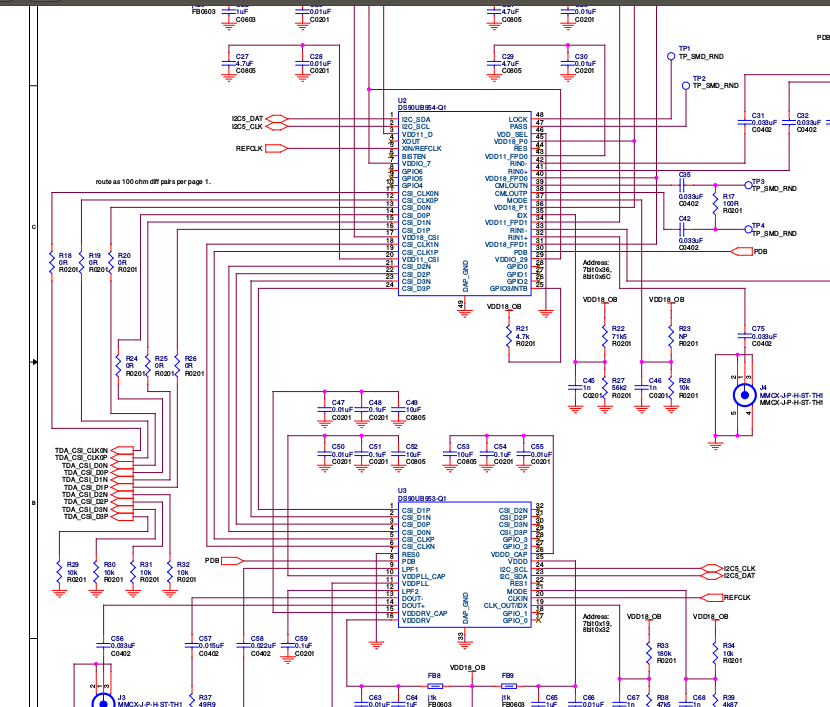
We are working with AR0220 camera sensor + UB953/UB954 SERDES on custom TDA2P board.

Earlier we were working on TDA2Px-EVM with AR0220 and SERDES which was working. We have taken the same working configurations on custom board.

But we are getting I2C bust busy error as shown below,

"

Serilaizer # 0 has I2CAddr 74 !!!
Setting GPIO RST Pin
GPIO RST Pin setting DONE
src/bsp_deviceI2c.c @ Line 1567:
Bus busy detected recover I2C bus !!!
src/bsp_deviceI2c.c @ Line 667:
 I2C4: DEV 0x40: ERROR !!! 
 I2C4: Error timeout 5074 ms!!!
 Assertion @ Line: 507 in vision_sdk/apps/src/rtos/iss/src/common/app_util_iss.c!

"

We are using below settings in file "\apps\src\rtos\iss\src\sensor\iss_sensor_tda2px.c",

"

{SENSOR_AR0220,
        {
            4u,        /* I2C Instance id for the sensor */
            {0x40}, /* I2C Alias Address of the sensor */
            {0x74}, /* I2C Alias Address of the serializer */
            TRUE,     /* Flag for single/multi channel sensor config */
            SYSTEM_VIFW_4LANES,     /* Interface width */
            SYSTEM_VIFM_SCH_CSI2,    /* Video Interface mode - Single channel capture via CSI2 interface */
            SYSTEM_CSI2_RAW12,         /* Input CSI2 Data Format */
            0,    /* Virtual Channel Id */
            0,     /* Is CSI Enable Required in UB954 */
            {TRUE /* isCplxCfgValid */,
                 {{FALSE, 1}, /* Clock Lane */
                     {FALSE, 2}, /* data1Lane */
                     {FALSE, 3}, /* data2Lane */
                     {FALSE, 4}, /* data3Lane*/
                     {FALSE, 5}},/* data4Lane */
                     800 /* csi2PhyClk */ },
                     FVID2_VID_SENSOR_AR0220_DRV,         /* sensorDrvId */
                     FALSE,     /* sensorBroadcast */
                     FALSE,   /* enableFsin */
                    {0x36} /* I2C address of deserializer */

}}

"

Can anyone suggest how do we solve I2C bus busy error.

Regards,

Abhay

  • Hi Abhay,

    Do you have any other device connected to i2c address 0x74? Can you check? 

    Btw, are you able to communicate with the UB960 and it is setup correctly? please confirm..

    Regards,

    Brijesh 

  • Hi Brijesh,

    We have no other device connected to i2c address 0x74. We are using UB954 and not UB960.

    We have below devices connected over i2c,

    AR0220 sensor at i2c address 0x10
    UB954 deserializer at i2c address 0x36
    UB953 serializer at i2c address 0x18
    one more UB953 serializer at i2c address 0x19 &
    EEPROM at i2c address 0x50

    We are able to communicate with UB953/UB954 over i2c.

    Regards,
    Abhay

  • Hi Abhay,

    ok, so are you able to talk to sensor??

    Regards,
    Brijesh
  • Hi Brijesh,

    With SERDES connected, we are not able to talk to sensor. We are getting "Bus busy error" before writing to sensor.
    Also please note, we have enabled the back channel with SERDES.
    Without SERDES , we are able to write to the sensor.

    Regards,
    Abhay
  • Hi Abhay,

    Since you are able to talk to UB953, back channel is established.
    when you see this error, can you check if you are still able to talk to ub953 serializer?

    Regards,
    Brijesh
  • Hi Brijesh,

    I am working with Abhay on this issue.

    We are able to read the Serialiser ID,but not able to probe the sensor.

    We are getting assertion at the end.


    [IPU1-0]     26.436100 s: Serilaizer # 0 has I2CAddr 74 !!!   -----------------------------------Alias Address of Serialiser
    [IPU1-0]     32.116574 s: Deserializer I2C address 0x36 Probe SUCCESS
    [IPU1-0]     32.117580 s: Serializer I2C address 0x18 Probe SUCCESS
    [IPU1-0]     32.117916 s: Read from register 0x5b of deser is successful, SER ID = 30 ...
    [IPU1-0]     32.118251 s: Read from register 0x5C of deser is successful, SER ALIAS ID = e8 ...
    [IPU1-0]     32.118587 s: Read from register 0x5E of deser is successful, SER ALIAS ID = e8 ...
    [IPU1-0]     32.118922 s: Read from register 0x65 of deser is successful, 1st Alias Slave ID = 30 ...
    [IPU1-0]     32.119044 s: Bsp_deviceI2cProbeDevice serializer start.......
    [IPU1-0]     32.120295 s: Bsp_deviceI2cProbeDevice serializer is successful for 7 bit address 0x18 ...
    [IPU1-0]     32.120661 s: Reading reg 0x00 from serialiser is successful, value = 30 ...
    [IPU1-0]     32.131184 s: Sensor I2C Address Probe FAILED !!!!!!!!
    [IPU1-0]     32.136491 s: src/bsp_deviceI2c.c @ Line 1567:
    [IPU1-0]     32.136582 s: Bus busy detected recover I2C bus !!!
    [IPU1-0]     32.136674 s: src/bsp_deviceI2c.c @ Line 667:
    [IPU1-0]     32.136765 s:  I2C4: DEV 0x10: ERROR !!!
    [IPU1-0]     32.136857 s: src/bsp_deviceI2c.c @ Line 689:
    [IPU1-0]     32.136918 s:  I2C4: Error timeout 5 ms!!!
    [IPU1-0]     32.137009 s: AR0220_Start : status = ffffffed
    [IPU1-0]     32.137070 s: AR0220_WriteReg FAILED : Reg Addr = 10, Reg Val = 301a
    [IPU1-0]     37.147166 s: src/bsp_deviceI2c.c @ Line 667:
    [IPU1-0]     37.147288 s:  I2C4: DEV 0x10: ERROR !!!
    [IPU1-0]     37.147410 s: src/bsp_deviceI2c.c @ Line 689:
    [IPU1-0]     37.147501 s:  I2C4: Error timeout 5010 ms!!!
    [IPU1-0]     37.147562 s:  Assertion @ Line: 507 in apps/src/rtos/iss/src/common/app_util_iss.c!

    Thanks

    Deepika

  • Hi Deepika,

    Please check if sensor has to be brought out of reset/power is supplied to sensor?

    Regards,
    Sujith
  • Hi Sujith,

    The sensor is out of reset. We have taken sensor out of reset before writing to serdes and sensor.
    Previously, with the working setup (on EVM), we had a separate serializer + sensor module and we were communicating to the sensor using back channel. Now with present custom board setup, all the three (Ser, deser & sensor) are on I2C5.
    So is it possible that TDA2P is talking to sensor over I2C5 and at the same time SERDES is also talking to sensor over I2C5, is it possible that this may cause that I2C buss error is our case ?

    Regards,
    Abhay
  • Abhay,

    They are independent. deserializer is on i2c5, but we need to talk to deserializer to talk to sensor. When we provide aliased address, it converts into actual address and talks to remote device over back channel..
    Are you working in synchronous mode? Also can you read some status register on UB953 to check status of sensor?

    Rgds,
    Brijesh
  • hi Abhay,

    Can you please probe and check if SCL held high.

    Regards,
    Sujith
  • Hi Sujith,

    Currently working with MCSPI issue that we are facing. I will check this next week and update you accordingly.

    Thanks,
    Abhay
  • Hi Sujith,

    We have fixed the bus busy error by disabling the Back channel from Serializer(953) as well as from Deserializer(954).

    We are now able to  probe the sensor and read/write its register.

    From schematics we see that

    from sensor(4 lanes)---->SER=====FPD LINK=========DESER(2 lanes)-----------TDA2P

    We have modified the structure as follows:

    {SENSOR_AR0220,

           {

    4u, /* I2C Instance id for the sensor */

    {0x10}, /* I2C Address of the sensor */

    {0x18}, /* I2C Address of the serializer */

    TRUE, /* Flag for single/multi channel sensor config */

    SYSTEM_VIFW_2LANES                   / *SYSTEM_VIFW_4LANES*/, /* Interface width */

    SYSTEM_VIFM_SCH_CSI2, /* Video Interface mode - Single channel capture via CSI2 interface */

               SYSTEM_CSI2_RAW12, /* Input CSI2 Data Format */

    0, /* Virtual Channel Id */

               0, /* Is CSI Enable Required in UB954 */

               {TRUE /* isCplxCfgValid */,

                    {{TRUE, 1}, /* Clock Lane */

                        {TRUE, 2}, /* data1Lane */

                         {   TRUE, 3}}, /* data2Lane */

                        400 /* csi2PhyClk */ },

                        FVID2_VID_SENSOR_AR0220_DRV,  /* sensorDrvId */

                        FALSE,     /* sensorBroadcast */

                        FALSE,   /* enableFsin */

    {0x36}}}

    };

    I have highlighted the main changes. Polarity kept TRUE as we have N/P configuration.

    Does this looks ok??

    Regards,

    Abhay

  • Hi Sujith,

    One more doubt, what changes are required in SerDes register configuration if the lane polarity is different than the working setup.


    Regards,
    Abhay
  • Hi Sujith,

    Do you any update on this.

    Thanks,
    Abhay
  • Hi Abhay,

    To operate UB954 in 2 lane mode you will have to set register 0x33 bits 5:4 to 2. In the PDK demo application, by default we use 4 lanes and we set register 0x33 with 0x3.

    If the same were to be operate in 2 lane mode, we would have set register 0x33 with 0x23.

    regards,
    Sujith
  • Hi Sujith,

    Thanks for your reply.
    One more doubt,is the processor side configuration as shown above is ok??

    We have 2 lanes from 954(DESER) is going again to another 953 (SER) with addr 0x19.
    So,do we need CSI2 in replicate mode in DESER so that the 2 lane of data will go to TDA2P and another 2 lane will go to 953 Serializer.

    Regards,
    Deepika

  • Hi Sujith,

    We have 25MHz REFCLK for Deserializer and a separate 25MHz CLKIN for Serializer.
    Will thye device work only in ASYNC mode?

    The value of AC Coupling capacitor is 33pF.It is mentioned in the datasheet that for Async Mode we need 100nF and for Sync Mode 33pF AC Coupling Capacitance is required.Now with this configuration will ASYNC Mode work?

    While probing I am not getting any CSI2 Clock or Data.

    Thanks
    Deepika
  • Hi Deepika,

    It's quite confusing, as stated by Abhay the signal chain is sensor(4 lanes)---->SER=====FPD LINK=========DESER(2 lanes)-----------TDA2P
    Is this correct or do you have one more serdes combination before the TDA2P?

    Regards,
    Sujith
  • Also, can you please detail the complete signal chain. Please include the crystals used for each component.

    Regards,
    Sujith
  • Hi Sujith,

    Sorry for making it confused.

    Please see the below diagram for more clarity. As you can see from the figure all the components (SER,DESER and  AR0220 ) have separate clocks and they are connected independently to TDA2P through I2C.

    I am getting CSI2 Clock from the sensor, but due to incorrect configuration of SERDES no CS2 CLK or data is coming to TDA2P.

    Following are my configurations for SER and DESER

    BspUtils_Ub960I2cParams gAppIssUtilsUb954Cfg_AR0220_CSI2_DesCfg[AR0220_CSI2_DES_CFG_SIZE] = {

        {0x0C, 0x83, 0x10},  
        {0x1F, 0x03, 0x10}, /* 400 CSI Freq */
        {0x4C, 0x01, 0x1},        /*Page FPD3 port RX0 registers for R/W*/
        {0x58, 0x1C , 0x1},        /*Enable and set backchannel rate to 10Mbs for Async Mode/ I2C passthrough disabled*/
        {0x5C, 0x30, 0x1},        /*set serializer alias to Ox18 (7-bit)*/
        {0x5D, ((uint8_t) (UB953_I2C_ADDRESS << 1U)), 0x0},
        {0x65, ((uint8_t) (UB953_I2C_ALIAS_ADDRESS << 1U)), 0x0},
        {0x5E, ((uint8_t) (AR0220_I2C_ADDRESS << 1U)), 0x0},

        {0x6D, 0x7C, 0x1},        /*CSI and coax mode*/
        {0xD5, 0xF2, 0x1},       /* Set AEQ MIN/MAX widest values*/
       {0x7C, 0x01, 0x1},        /* disabled FV Polarity */
       

        {0x32, 0x01, 0x1},        /*CSI0 select*/
        {0x33, 0x23, 0x1},        /*CSI_EN & CSI0 2L Continuous clock*/
        {0x21, 0x81, 0x1},        /*CSI Replicate mode SYNC disabled RR enabled */
        {0x20, 0x00, 0x1},         /*Rx Forwarding Enabled */
        {0xB9, 0x18, 0x1},        /*ENABLE PARITY ERROR COUNT*/
        {0x42, 0x71, 0x1},        /*ENABLE S-Filter with AEQ*/
      
    }


    BspUtils_Ub960I2cParams gUB953_AR0220_CSI2_SerCfg[AR0220_CSI2_SER_CFG_SIZE] = {


        {0x02, 0x73, 0x10},  /*4Lanes Continuous CLK 1.8V */
        {0x20, 0x1F, 0x10}, // CSI_POL_SEL changes for N/P Polarity
        {0x21, 0x1F, 0x10},
        {0x32, 0x09, 0x10}, /*I2C Pass through Disabled */
        {0x06, 0x21, 0x10},
        {0x07, 0x28, 0x10},

    Regards,

    Deepika

  • Hi Sujith,

    I was able to get Clock and Data from CSI2 Port in TDA2P side.

    But the picture is not clear. I am facing CRC errors in the Serdes Link.

    I tried with 400 and 800Mbps both from Deserializer and TDA2P.

    I disabled the  errorCallback() call in the file issCaptureLink_drv.c and got the following image on the display.

    Please give your suggestions,

    Regards,

    Deepika

  • Hi Deepika, Can you please check on the number of data lanes being used in the de-serializer and TDA2Px. It seems like 1/3 of line is missing but these seems to be some kind of image in the background. Regards, Sujith
  • Hi Sujith,
    Thanks for reply.
    We have set register 0x33 to 0x23 in deserialiser as we have 2 lanes connected to TDA2P.

    Yes,in background there is some image.Is this type of image is a result of some clocking issue?

    Regards,
    Deepika
  • Hi Sujith,

    One more info, while reading CSI_RX_STS(0x7A) and CSI_ERR_COUNTER(0x7B) from the Deserialiser(954) I am getting the following values:
    CSI_RX_STS(0x7A) = 0x02
    CSI_ERR_COUNTER(0x7B)=0X01

    Can this also cause problem?
    Also do you have any suggestions for getting the full image on the screen?

    I am attaching a part of schematics showing connections between Deser(954) and CSI Clk and Data lanes going to TDA2P


    Regards,
    Deepika

  • Hi Deepika, Register CSI_RX_STS with value of 0x02 indicates that there were > 1 bit ECC error. Which cannot be corrected by h/w. Can you please check on the following 1. UB954 clear the error status / counters and re-read the same register. Check if the error persists. I suspect this error is persistent 2. Check if this error source is UB953/Sensor Regards, Sujith
  • Hi Sujith,

    I tried reading CSI_RX_STS(0x7A) and CSI_ERR_COUNTER(0x7B).I have created a loop to read the two registers.Only once I am getting 1 bit ECC error,after reading it again the registers are cleared.On re reading it, it reads 0.


    [IPU1-0] 26.560269 s: Read from register CSI_RX_STS(0x7A):: = 2 ...
    [IPU1-0] 26.560605 s: Read from register CSI_ERR_COUNTER(0x7B):: = 1 ...


    [IPU1-0] 26.563533 s: Read from register CSI_RX_STS(0x7A):: = 0 ...
    [IPU1-0] 26.563868 s: Read from register CSI_ERR_COUNTER(0x7B):: = 0 ...

    [IPU1-0] 26.566339 s: Read from register CSI_RX_STS(0x7A):: = 0 ...
    [IPU1-0] 26.566674 s: Read from register CSI_ERR_COUNTER(0x7B):: = 0 ...

    [IPU1-0] 26.569328 s: Read from register CSI_RX_STS(0x7A):: = 0 ...
    [IPU1-0] 26.569663 s: Read from register CSI_ERR_COUNTER(0x7B):: = 0 ...

    [IPU1-0] 26.572317 s: Read from register CSI_RX_STS(0x7A):: = 0 ...
    [IPU1-0] 26.572652 s: Read from register CSI_ERR_COUNTER(0x7B):: = 0 ...

    [IPU1-0] 26.575398 s: Read from register CSI_RX_STS(0x7A):: = 0 ...
    [IPU1-0] 26.575733 s: Read from register CSI_ERR_COUNTER(0x7B):: = 0 ...

    [IPU1-0] 26.578539 s: Read from register CSI_RX_STS(0x7A):: = 0 ...
    [IPU1-0] 26.578875 s: Read from register CSI_ERR_COUNTER(0x7B):: = 0 ...

    [IPU1-0] 26.581345 s: Read from register CSI_RX_STS(0x7A):: = 0 ...
    [IPU1-0] 26.581681 s: Read from register CSI_ERR_COUNTER(0x7B):: = 0 ...

    [IPU1-0] 26.584334 s: Read from register CSI_RX_STS(0x7A):: = 0 ...
    [IPU1-0] 26.584670 s: Read from register CSI_ERR_COUNTER(0x7B):: = 0 ...

    [IPU1-0] 26.587384 s: Read from register CSI_RX_STS(0x7A):: = 0 ...
    [IPU1-0] 26.587720 s: Read from register CSI_ERR_COUNTER(0x7B):: = 0 ...

    Also the RX_PORT_STS2(0x4E) reads 0x4D ----Which means CSI Receive error detected.
    SENSOR_STS_0 (0x51) and SENSOR_STS_3(0x54) reads 0.


    Apart from this I wanted to inform you that even though we have a 25MHz CLK_IN to the serialiser we have changed the MODE Register(0x03) of serialiser to 0x10 to make it work in Sync mode.

    Regards,
    Deepika

  • Hi Sujith,

    I am running the PDK  demo application for checking the Colour Bar pattern generation by using the following test id:

    {"Sensor Config Bypassed CSI2 4Lanes capture color bars from UB954",   0U,

        TRUE,

        FVID2_VIFM_SCH_CSI2,

        FVID2_VIFW_2LANES, 1U, 0U, VPS_ISS_CAL_CSI2_RAW12,FVID2_BPP_BITS12,

        CAPT_APP_RUN_COUNT, 1280U, 720U, (720U * 3U),

        FVID2_VID_SENSOR_BYPASS_CSI2_DRV,

        FVID2_STD_1080P_30, FVID2_DF_BAYER_BGGR, FVID2_BPP_BITS12,

        BSP_BOARD_MODE_DEFAULT},

    I have cofigured it for 2 Lanes,But I want the polarity to be reversed.

    the value of 0x489B0304  is 0x4A000321.

    This is for P/N Polarity. For the custom board polarity is N/P. How can I make that configuration.

    Regards,

    Deepika

  • Hi Deepika, Please check the function appCaptDeriveCfg (), by default it's set to pCmplxIoCfg->clockLane.pol = FALSE; You might have to make it pCmplxIoCfg->clockLane.pol = TRUE; Regards, Sujith
  • Hi Sujith,

    By changing the lane polarity  and keeping the already available pattern generation code in bsputils_ub95x.c  the COMPLEXIO_CFG Register is out of reset  is the value of 0x489B0304  is 0x6A000BA9.

    By probing the clock and 2 data lanes we are getting data but no clock,and  we are not getting  anything on HDMI.

    It is stuck at "Starting Capture now"

    This is what I have added for polarity and position.Is there anything we are missing out.

    if (FVID2_VID_SENSOR_BYPASS_CSI2_DRV == pCfg->sensorDrvId)
        {
            pCmplxIoCfg->clockLane.pol      = TRUE;
            pCmplxIoCfg->clockLane.position = 1U;
            pCmplxIoCfg->data1Lane.pol      = TRUE;
            pCmplxIoCfg->data1Lane.position = 2U;
            pCmplxIoCfg->data2Lane.pol      = TRUE;
            pCmplxIoCfg->data2Lane.position = 3U;

    Regards,

    Deepika

  • Hi Sujith,

    I was going through the datasheet of 954 ,in the datasheet  Section 7.4.21 CSI-2 Transmitter Frequency


    There is no description of REF_CLK_MODE in the datasheet.

    Also I am not understanding the reason for not getting CSI_CLK output from the Deserialiser.Also there is no voltage level on the CSI_CLK line...it is 700mV. Is this Ok?

    Lane order and polarity have already been mapped and cross checked.

    Regards,

    Deepika

  • Hi Sujith,

    We are not still not getting any clue.Can you please guide us on this.

    Regards,
    Deepika
  • Hi Deepika, Let me check this out on TI EVM with UB954 EVM on 2 lanes with color bars and come back to you. Regards, Sujith
  • Hi Sujith,

    Just for information..I was checking the schematics of the Custom board..In the MODE pin  R HIGH is open and RLOW  is 10K..Due to this it should work in CSI2 Async Back Channel Mode

  • Hi Deepika,

    Let me check with FPD Link expert on this.

    Regards,
    Sujith
  • Hi Sujith,

    Did you get time to check this.

    Regards,
    Abhay
  • Hi Sujith,

    I am writing 0x33(CSI_CTL) to 0x23 for 2 Lane continuous Clock Mode . But when I read this value after writing it shows me only 0x3 instead of 0x23(which I have actually written).Is this an issue?

    Regards,
    Deepika
  • Hi Deepika, Yes, that could be an issue. Can you please check on the following 1. Verify if the first write is OK. 2. Identify after which register write, this value is being reset. In parallel, i am trying with TDA2Px board. I will update you as soon as i have progress. Regards, Sujith
  • Hi Sujith,

    The first write itself is not working.I disabled continuous CLK from 0x33..I disabled continuous clock from serialiser too,still the value is coming as 3.
    I am reading the registers after all the registers of structure array are written.

    Regards,
    Deepika
  • Hi Deepika,

    Can you confirm if register 0x21 of UB954 and CSI_REPLICATE is set?

    Regards,
    Sujith
  • Hi Sujith,


    Yes ,it is set. This is the order in which I am setting the registers.

    {0x0C, 0x83, 0x10}, /*Enable PORT0 and PORT1 Receiver */
    {0x1F, 0x02, 0x10}, /* 800 CSI Freq */

    {0x20, 0x20, 0x1}, /*Rx Forwarding Enabled for RX0 disabled for RX1 */

    {0x4C, 0x01, 0x1}, /* FPD3 port RX0 registers for R/W*/
    {0x21, 0x81, 0x1}, /*CSI Replicate mode SYNC disabled RR enabled*/
    {0x58, 0x1E , 0x1}, /*Enable and set backchannel rate to 50Mbs for sync Mode/ I2C passthrough disabled Back Channel Enable*/
    {0x6D, 0x78, 0x1}, /*CSI and STP mode */
    {0x32, 0x01, 0x1}, /*CSI0 select*/
    {0x33, 0x23, 0x1}, /*CSI_EN & CSI0 2L Continuous clock*/

    Do we have any errata document of 954 so that we can check if we have missed out on any point.

    Thanks,
    Deepika

  • Hi Sujith,

    I have disabled replicate mode now.
    After the writing of all the configurations,i tried writing 0x33 to 0x21 ,added a 20ms delay and read back.The value was coming 0x21.But I am not able to find out due to which configuration the value of 0x33 is changing.

    Regards,
    Deepika
  • Hi Sujith,

    I tried reading the CSI_CTL(0x33) from the file issCaptureLink_drv.c in the function IssCaptureLink_drvProcessData().Again the value is coming 0x3,instead of 0x21. Is there any clue what can make that value change.

    Regards,
    Deepika
  • Hi Deepika, I cant explain, which the number of lanes changes. Can you please share the UB953 & UB954 configurations? Regards, Sujith
  • Hi Sujith,

    PLease find my SER DES configuration

    BspUtils_Ub960I2cParams gAppIssUtilsUb954Cfg_AR0220_CSI2_DesCfg[AR0220_CSI2_DES_CFG_SIZE] = {


    {0x0C, 0x83, 0x10}, /*Enable PORT0 and PORT1 Receiver */
    {0x1F, 0x02, 0x10}, /* 800 CSI Freq */

    {0x20, 0x00, 0x1}, /*Rx Forwarding Enabled for RX0 disabled for RX1 */

    {0x4C, 0x01, 0x1}, /* FPD3 port RX0 registers for R/W*/
    {0x21, 0x81, 0x1}, /*CSI Replicate mode SYNC disabled RR enabled*/

    {0x58, 0x1E , 0x1}, /*Enable and set backchannel rate to 50Mbs for sync Mode/ I2C passthrough disabled Back Channel Enable*/
    {0x6D, 0x78, 0x1}, /*CSI and STP mode*/
    {0x32, 0x01, 0x1}, /*CSI0 select*/
    {0x33, 0x23, 0x1}, /*CSI_EN & CSI0 2L Continuous clock*/


    };


    BspUtils_Ub960I2cParams gUB953_AR0220_CSI2_SerCfg[AR0220_CSI2_SER_CFG_SIZE] = {
    {0x02, 0x73, 0x10}, /*4Lanes Continuous CLK 1.8V */
    {0x03, 0x10, 0x10}, /*Changing MODE register for overriding strap value to make it work in synchronous mode*/
    {0x32, 0x09, 0x10}, /*Keeping it to default value I2C Pass through disabled */
    };


    Regard,
    Deepika
  • Hi Sujith,

    As discussed in the call today I tried streaming  with 2 lanes on 954 EVM and TDA2P EVM. I did the following changes:

    1) In the file iss_sensor_tda2px.c  I kept 2 lanes configuration

                       FALSE}},   /* enableFsin */
        {SENSOR_AR0220,
                {
                        4u,         /* I2C Instance id for the sensor */
                        {0x40}, /* I2C Address of the sensor */
                        {0x74}, /* I2C Address of the serializer */
                        TRUE,       /* Flag for single/multi channel sensor config */
                        SYSTEM_VIFW_2LANES,         /* Interface width */
                        SYSTEM_VIFM_SCH_CSI2,       /* Video Interface mode - Single channel capture via CSI2 interface */
                        SYSTEM_CSI2_RAW12,          /* Input CSI2 Data Format */
                        0,  /* Virtual Channel Id */
                        0,  /* Is CSI Enable Required in UB954 */
                        {TRUE /* isCplxCfgValid */,
                                {{FALSE, 1}, /* Clock Lane */
                                        {FALSE, 2}, /* data1Lane */
                                        {FALSE, 3}}, /* data2Lane */        
                                800 /* csi2PhyClk */ },
                        FVID2_VID_SENSOR_AR0220_DRV,  /* sensorDrvId */
                        FALSE,     /* sensorBroadcast */
                        FALSE,      /* enableFsin */
                        {0x30}        

    2)Commented the CRC error check in issCaptureLink_drv.c.

    3) Changed the value of 0x33 to 0x23 (2 Lane Continous clock Mode)

    Reading this register again gives 0x3 as it is happening in the custom board.

    And I am getting the similar image which I got in the custom board. I am attaching the image for your reference.

    Regards,

    Deepika

  • Hi Deepika, Thanks, this indicates that we have an issue with UB954/UB953 configuration. I am looking at the configurations values that you had provided earlier, i will update you on the observations. Regards, Sujith
  • Hi Sujith,

    The only register from the working condition of SERDES that I changed was 0x33. Also even there was 4 lane connection from the TDA2P side I changes to 2 Lanes from Software

    Thanks
    Deepika

  • Hi Deepika, With the EVM setup, did you have to override the mode in UB953? Regards, Sujith
  • Hi  Sujith

    No ..it was already working in sync mode.So no overriding was required

    Thanks,

    Deepika

  • Hi Sujith,

    One more finding..I have not changed the value of 0x33.Its value is 0x3 right now.

    Now only two changes are there:

    1)No of lanes in the tda2p side is 2
    2)CRC check has been commented in the issCaptureLink_drv.c.

    Still we are getting the same image as we got.

    Regards,
    Deepika