This thread has been locked.

If you have a related question, please click the "Ask a related question" button in the top right corner. The newly created question will be automatically linked to this question.

RTOS/CC2640: ADC driver question

Part Number: CC2640
Other Parts Discussed in Thread: CC2650

Tool/software: TI-RTOS

CC2640 4x4 custom board, TI RTOS 2.20.1.08, ble_sdk_2_02_01_18,

simple_peripheral_cc2650_lp_app.

Is a dedicated pin needed on the board when defining the hardware

attributes of the ADC driver? (HW attribute definitions attached for

both uart and adc drivers).

The application uses both the UART and ADC drivers, but never at the

same time. If there is no activity on the UART_RX pin, the UART_RX becomes

the analog input pin to the ADC driver.

The ADC driver by itself is working fine in the application. When the UART is used,

(only for sensor calibration, with communication to an external processor), the sensor

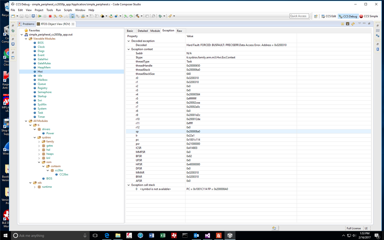
reaches a hard fault exception and fails to communicate properly through the UART

(screenshot attached).

When the UART is in use, I'm wondering if the ADC driver is being accessed without

being powered on causing this exception.

Thanks,

Priya

const ADCCC26XX_HWAttrs adcCC26xxHWAttrs[1] = {
    {
        .adcDIO = Board_UART_RX,
        .adcCompBInput = ADC_COMPB_IN_AUXIO3,
        .refSource = ADCCC26XX_FIXED_REFERENCE,
        .samplingDuration = ADCCC26XX_SAMPLING_DURATION_2P7_US,
        .inputScalingEnabled = true,
        .triggerSource = ADCCC26XX_TRIGGER_MANUAL
    },

};

const UARTCC26XX_HWAttrsV1 uartCC26XXHWAttrs[CC2650_LAUNCHXL_UARTCOUNT] = {
    {
        .baseAddr       = UART0_BASE,
        .powerMngrId    = PowerCC26XX_PERIPH_UART0,
        .intNum         = INT_UART0_COMB,
        .intPriority    = ~0,
        .swiPriority    = 0,
        .txPin          = Board_UART_TX,
        .rxPin          = Board_UART_RX,
        .ctsPin         = PIN_UNASSIGNED,
        .rtsPin         = PIN_UNASSIGNED
    }
};

  • When you are done with UART, did you close the uart driver and make sure the pins are available for ADC again?
  • Christin,

    Thank you for your reply.

    To simplify debugging, I am trying to use the UART on the sensor with

    ble_sdk_2_02_01_18; but without opening or using the ADC driver.

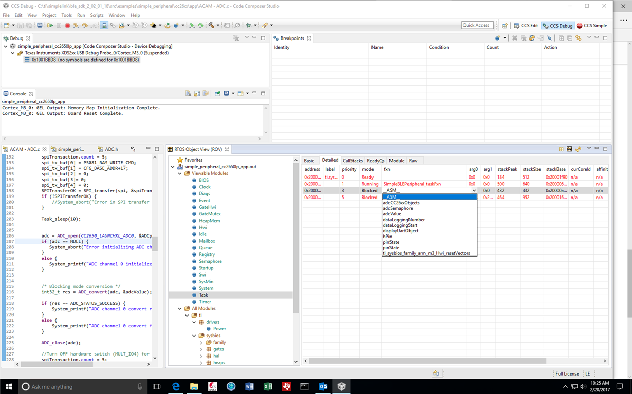
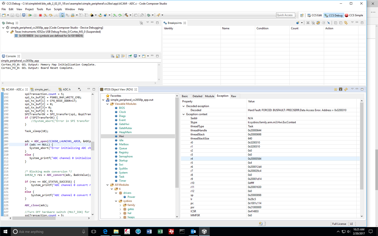
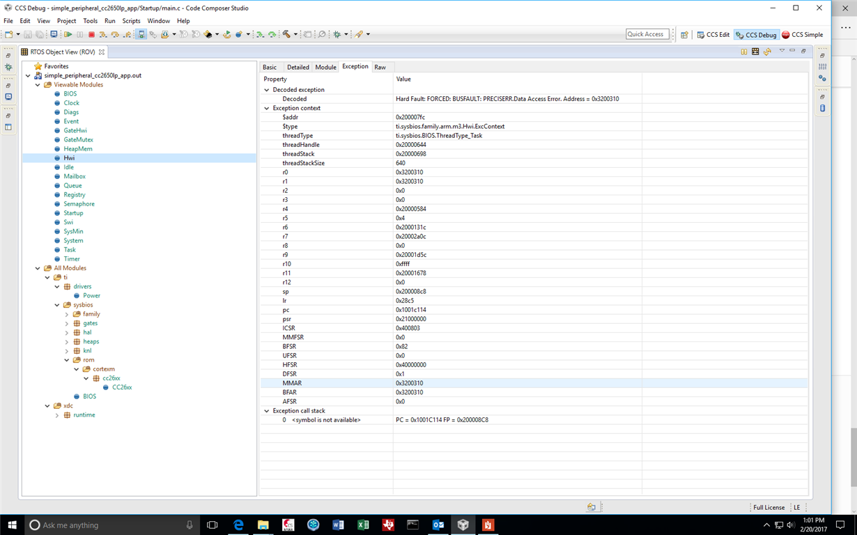
    I am seeing the same problem with the sensor (screenshots attached).

    Is this a problem with the stack sizes after the stack upgrade? Which

    task stack size should I increase and how?

    FYI-- I am working under the assumption my board file set up is OK.

    I am using the same directory structure as the  CC2650_LAUNCHXL

    with the board files edited to reflect the custom board pins.  Let me

    know if a board file review will help, I will upload it. (The pin to

    schematic mapping has been checked many times, this is not what I

    want checked here).

    Thanks,

    Priya

  • I followed the steps from SWDG 9.8.2 to decode this exception. The

    decoded symbol is not available. I also increased the gapRole_taskFxn

    task size slightly, so the task module in ROV is not showing any stack

    peaks being reached.

    This exception does not happen with the use of the UART in

    ble_sdk_2_02_00_31. This stack however does not have the ADC driver.

    Any pointers are much appreciated.

    Thanks,

    Priya

  • The lr pointed to the following section in simple_peripheral_task_fxn:
    // If RTOS queue is not empty, process app message.
    while (!Queue_empty(appMsgQueue))
    {

    sbpEvt_t *pMsg = (sbpEvt_t *)Util_dequeueMsg(appMsgQueue);

    if (pMsg)
    {
    // Process message.
    SimpleBLEPeripheral_processAppMsg(pMsg);
    // Free the space from the message.
    ICall_free(pMsg);

    }
    }
    }

    I added the HEAPMGR_Metrics preprocessor option. There was nothing
    in the global variables that indicated a problem. I did not have success
    calling internal functions like heapmgrSanityCheck() (could not get
    past compile errors).

    I will await pointers on what to do from here.

    Thanks,
    Priya
  • Hi,

    Thanks for providing all the information.

    You said the same program works on BLE stack 2.2.0 and the only difference between now and then is that you added ADC driver into your board file without initializing it? Can you attach your board file?
  • Christin,

    The ble_sdk_2_02_00_31 project has its own independent custom board directory.

    Several board files/bleUserConfig were edited to make this a pre-processor symbol.

    For the ble_sdk_2_02_01_18 project, I tried making custom CC2650_LAUNCHXL

    board files and not using an independent custom board directory. This

    probably is a factor in why the sensor is not talking through the UART like

    the ble_sdk_2_02_00_31 project. I am currently not opening the ADC driver at all

    in the ble_sdk_2_02_01_18 project.

    The ble_sdk_2_02_01_18 board files are attached for review.

    Thank you,

    Priya

    CC2650_LAUNCHXL - custom.c
    /*
     * Copyright (c) 2016, Texas Instruments Incorporated
     * All rights reserved.
     *
     * Redistribution and use in source and binary forms, with or without
     * modification, are permitted provided that the following conditions
     * are met:
     *
     * *  Redistributions of source code must retain the above copyright
     *    notice, this list of conditions and the following disclaimer.
     *
     * *  Redistributions in binary form must reproduce the above copyright
     *    notice, this list of conditions and the following disclaimer in the
     *    documentation and/or other materials provided with the distribution.
     *
     * *  Neither the name of Texas Instruments Incorporated nor the names of
     *    its contributors may be used to endorse or promote products derived
     *    from this software without specific prior written permission.
     *
     * THIS SOFTWARE IS PROVIDED BY THE COPYRIGHT HOLDERS AND CONTRIBUTORS "AS IS"
     * AND ANY EXPRESS OR IMPLIED WARRANTIES, INCLUDING, BUT NOT LIMITED TO,
     * THE IMPLIED WARRANTIES OF MERCHANTABILITY AND FITNESS FOR A PARTICULAR
     * PURPOSE ARE DISCLAIMED. IN NO EVENT SHALL THE COPYRIGHT OWNER OR
     * CONTRIBUTORS BE LIABLE FOR ANY DIRECT, INDIRECT, INCIDENTAL, SPECIAL,
     * EXEMPLARY, OR CONSEQUENTIAL DAMAGES (INCLUDING, BUT NOT LIMITED TO,
     * PROCUREMENT OF SUBSTITUTE GOODS OR SERVICES; LOSS OF USE, DATA, OR PROFITS;
     * OR BUSINESS INTERRUPTION) HOWEVER CAUSED AND ON ANY THEORY OF LIABILITY,
     * WHETHER IN CONTRACT, STRICT LIABILITY, OR TORT (INCLUDING NEGLIGENCE OR
     * OTHERWISE) ARISING IN ANY WAY OUT OF THE USE OF THIS SOFTWARE,
     * EVEN IF ADVISED OF THE POSSIBILITY OF SUCH DAMAGE.
     */
    
    /*
     *  ====================== CC2650_LAUNCHXL.c ===================================
     *  This file is responsible for setting up the board specific items for the
     *  CC2650 LaunchPad.
     */
    
    
    /*
     *  ====================== Includes ============================================
     */
    #include <xdc/std.h>
    #include <xdc/runtime/System.h>
    
    #include <ti/sysbios/family/arm/m3/Hwi.h>
    #include <ti/drivers/PIN.h>
    #include <ti/drivers/pin/PINCC26XX.h>
    #include <ti/drivers/PWM.h>
    #include <ti/drivers/pwm/PWMTimerCC26XX.h>
    #include <ti/drivers/timer/GPTimerCC26XX.h>
    #include <ti/drivers/Power.h>
    #include <ti/drivers/power/PowerCC26XX.h>
    
    #include <inc/hw_memmap.h>
    #include <inc/hw_ints.h>
    #include <driverlib/ioc.h>
    #include <driverlib/udma.h>
    
    #include "Board.h"
    
    /*
     *  ========================= IO driver initialization =========================
     *  From main, PIN_init(BoardGpioInitTable) should be called to setup safe
     *  settings for this board.
     *  When a pin is allocated and then de-allocated, it will revert to the state
     *  configured in this table.
     */
    /* Place into subsections to allow the TI linker to remove items properly */
    #if defined(__TI_COMPILER_VERSION__)
    #pragma DATA_SECTION(BoardGpioInitTable, ".const:BoardGpioInitTable")
    #pragma DATA_SECTION(PINCC26XX_hwAttrs, ".const:PINCC26XX_hwAttrs")
    #endif
    
    const PIN_Config BoardGpioInitTable[] = {
    
    	    Board_HGM_OUT | PIN_GPIO_OUTPUT_EN | PIN_GPIO_LOW | PIN_PUSHPULL,
    	    Board_PAEN_OUT |  PIN_GPIO_OUTPUT_EN | PIN_GPIO_LOW | PIN_PUSHPULL,
    		Board_EN_OUT |  PIN_GPIO_OUTPUT_EN | PIN_GPIO_LOW | PIN_PUSHPULL,
    
    		Board_ACSN | PIN_GPIO_OUTPUT_EN | PIN_GPIO_HIGH | PIN_PUSHPULL,
    
    		Board_UART_TX    | PIN_GPIO_OUTPUT_EN | PIN_GPIO_LOW   | PIN_PUSHPULL,
    		Board_UART_RX    | PIN_INPUT_EN | PIN_PULLDOWN   | PIN_HYSTERESIS,
    
    		Board_SPI0_MISO   | PIN_INPUT_EN | PIN_PULLUP | PIN_HYSTERESIS,
    		Board_SPI0_MOSI   | PIN_GPIO_OUTPUT_EN | PIN_GPIO_LOW | PIN_PUSHPULL,
    		Board_SPI0_CLK    | PIN_GPIO_OUTPUT_EN | PIN_GPIO_LOW | PIN_PUSHPULL,
    
    		Board_SPI_FLASH_CS   | PIN_GPIO_OUTPUT_EN | PIN_GPIO_HIGH | PIN_PUSHPULL,
    
        PIN_TERMINATE
    };
    
    const PINCC26XX_HWAttrs PINCC26XX_hwAttrs = {
        .intPriority = ~0,
        .swiPriority = 0
    };
    /*============================================================================*/
    
    /*
     *  ============================= Power begin ==================================
     */
    /* Place into subsections to allow the TI linker to remove items properly */
    #if defined(__TI_COMPILER_VERSION__)
    #pragma DATA_SECTION(PowerCC26XX_config, ".const:PowerCC26XX_config")
    #endif
    const PowerCC26XX_Config PowerCC26XX_config = {
        .policyInitFxn      = NULL,
        .policyFxn          = &PowerCC26XX_standbyPolicy,
        .calibrateFxn       = &PowerCC26XX_calibrate,
        .enablePolicy       = TRUE,
        .calibrateRCOSC_LF  = TRUE,
        .calibrateRCOSC_HF  = TRUE,
    };
    /*
     *  ============================= Power end ====================================
     */
    
    /*
     *  ============================= UART begin ===================================
     */
    /* Place into subsections to allow the TI linker to remove items properly */
    #if defined(__TI_COMPILER_VERSION__)
    #pragma DATA_SECTION(UART_config, ".const:UART_config")
    #pragma DATA_SECTION(uartCC26XXHWAttrs, ".const:uartCC26XXHWAttrs")
    #endif
    
    /* Include drivers */
    #include <ti/drivers/UART.h>
    #include <ti/drivers/uart/UARTCC26XX.h>
    
    /* UART objects */
    UARTCC26XX_Object uartCC26XXObjects[CC2650_LAUNCHXL_UARTCOUNT];
    
    /* UART hardware parameter structure, also used to assign UART pins */
    const UARTCC26XX_HWAttrsV1 uartCC26XXHWAttrs[CC2650_LAUNCHXL_UARTCOUNT] = {
        {
            .baseAddr       = UART0_BASE,
            .powerMngrId    = PowerCC26XX_PERIPH_UART0,
            .intNum         = INT_UART0_COMB,
            .intPriority    = ~0,
            .swiPriority    = 0,
            .txPin          = Board_UART_TX,
            .rxPin          = Board_UART_RX,
            .ctsPin         = PIN_UNASSIGNED,
            .rtsPin         = PIN_UNASSIGNED
        }
    };
    
    /* UART configuration structure */
    const UART_Config UART_config[] = {
        {
            .fxnTablePtr = &UARTCC26XX_fxnTable,
            .object      = &uartCC26XXObjects[0],
            .hwAttrs     = &uartCC26XXHWAttrs[0]
        },
        {NULL, NULL, NULL}
    };
    /*
     *  ============================= UART end =====================================
     */
    
    /*
     *  ============================= UDMA begin ===================================
     */
    /* Place into subsections to allow the TI linker to remove items properly */
    #if defined(__TI_COMPILER_VERSION__)
    #pragma DATA_SECTION(UDMACC26XX_config, ".const:UDMACC26XX_config")
    #pragma DATA_SECTION(udmaHWAttrs, ".const:udmaHWAttrs")
    #endif
    
    /* Include drivers */
    #include <ti/drivers/dma/UDMACC26XX.h>
    
    /* UDMA objects */
    UDMACC26XX_Object udmaObjects[CC2650_LAUNCHXL_UDMACOUNT];
    
    /* UDMA configuration structure */
    const UDMACC26XX_HWAttrs udmaHWAttrs[CC2650_LAUNCHXL_UDMACOUNT] = {
        {
            .baseAddr    = UDMA0_BASE,
            .powerMngrId = PowerCC26XX_PERIPH_UDMA,
            .intNum      = INT_DMA_ERR,
            .intPriority = ~0
        }
    };
    
    /* UDMA configuration structure */
    const UDMACC26XX_Config UDMACC26XX_config[] = {
        {
             .object  = &udmaObjects[0],
             .hwAttrs = &udmaHWAttrs[0]
        },
        {NULL, NULL}
    };
    /*
     *  ============================= UDMA end =====================================
     */
    
    /*
     *  ========================== SPI DMA begin ===================================
     */
    /* Place into subsections to allow the TI linker to remove items properly */
    #if defined(__TI_COMPILER_VERSION__)
    #pragma DATA_SECTION(SPI_config, ".const:SPI_config")
    #pragma DATA_SECTION(spiCC26XXDMAHWAttrs, ".const:spiCC26XXDMAHWAttrs")
    #endif
    
    /* Include drivers */
    #include <ti/drivers/spi/SPICC26XXDMA.h>
    
    /* SPI objects */
    SPICC26XXDMA_Object spiCC26XXDMAObjects[CC2650_LAUNCHXL_SPICOUNT];
    
    /* SPI configuration structure, describing which pins are to be used */
    const SPICC26XXDMA_HWAttrsV1 spiCC26XXDMAHWAttrs[CC2650_LAUNCHXL_SPICOUNT] = {
        {
            .baseAddr           = SSI0_BASE,
            .intNum             = INT_SSI0_COMB,
            .intPriority        = ~0,
            .swiPriority        = 0,
            .powerMngrId        = PowerCC26XX_PERIPH_SSI0,
            .defaultTxBufValue  = 0,
            .rxChannelBitMask   = 1<<UDMA_CHAN_SSI0_RX,
            .txChannelBitMask   = 1<<UDMA_CHAN_SSI0_TX,
            .mosiPin            = Board_SPI0_MOSI,
            .misoPin            = Board_SPI0_MISO,
            .clkPin             = Board_SPI0_CLK,
            .csnPin             = Board_SPI0_CSN
        },
        {
            .baseAddr           = SSI1_BASE,
            .intNum             = INT_SSI1_COMB,
            .intPriority        = ~0,
            .swiPriority        = 0,
            .powerMngrId        = PowerCC26XX_PERIPH_SSI1,
            .defaultTxBufValue  = 0,
            .rxChannelBitMask   = 1<<UDMA_CHAN_SSI1_RX,
            .txChannelBitMask   = 1<<UDMA_CHAN_SSI1_TX,
            .mosiPin            = Board_SPI1_MOSI,
            .misoPin            = Board_SPI1_MISO,
            .clkPin             = Board_SPI1_CLK,
            .csnPin             = Board_SPI1_CSN
        }
    };
    
    /* SPI configuration structure */
    const SPI_Config SPI_config[] = {
        {
             .fxnTablePtr = &SPICC26XXDMA_fxnTable,
             .object      = &spiCC26XXDMAObjects[0],
             .hwAttrs     = &spiCC26XXDMAHWAttrs[0]
        },
        {
             .fxnTablePtr = &SPICC26XXDMA_fxnTable,
             .object      = &spiCC26XXDMAObjects[1],
             .hwAttrs     = &spiCC26XXDMAHWAttrs[1]
        },
        {NULL, NULL, NULL}
    };
    /*
     *  ========================== SPI DMA end =====================================
    */
    
    
    /*
     *  ============================= I2C Begin=====================================
    */
    /* Place into subsections to allow the TI linker to remove items properly */
    #if defined(__TI_COMPILER_VERSION__)
    #pragma DATA_SECTION(I2C_config, ".const:I2C_config")
    #pragma DATA_SECTION(i2cCC26xxHWAttrs, ".const:i2cCC26xxHWAttrs")
    #endif
    
    /* Include drivers */
    #include <ti/drivers/i2c/I2CCC26XX.h>
    
    /* I2C objects */
    I2CCC26XX_Object i2cCC26xxObjects[CC2650_LAUNCHXL_I2CCOUNT];
    
    /* I2C configuration structure, describing which pins are to be used */
    const I2CCC26XX_HWAttrsV1 i2cCC26xxHWAttrs[CC2650_LAUNCHXL_I2CCOUNT] = {
        {
            .baseAddr = I2C0_BASE,
            .powerMngrId = PowerCC26XX_PERIPH_I2C0,
            .intNum = INT_I2C_IRQ,
            .intPriority = ~0,
            .swiPriority = 0,
            .sdaPin = Board_I2C0_SDA0,
            .sclPin = Board_I2C0_SCL0,
        }
    };
    
    /* I2C configuration structure */
    const I2C_Config I2C_config[] = {
        {
            .fxnTablePtr = &I2CCC26XX_fxnTable,
            .object = &i2cCC26xxObjects[0],
            .hwAttrs = &i2cCC26xxHWAttrs[0]
        },
        {NULL, NULL, NULL}
    };
    /*
     *  ========================== I2C end =========================================
     */
    
    /*
     *  ========================== Crypto begin ====================================
     *  NOTE: The Crypto implementation should be considered experimental
     *        and not validated!
     */
    /* Place into subsections to allow the TI linker to remove items properly */
    #if defined(__TI_COMPILER_VERSION__)
    #pragma DATA_SECTION(CryptoCC26XX_config, ".const:CryptoCC26XX_config")
    #pragma DATA_SECTION(cryptoCC26XXHWAttrs, ".const:cryptoCC26XXHWAttrs")
    #endif
    
    /* Include drivers */
    #include <ti/drivers/crypto/CryptoCC26XX.h>
    
    /* Crypto objects */
    CryptoCC26XX_Object cryptoCC26XXObjects[CC2650_LAUNCHXL_CRYPTOCOUNT];
    
    /* Crypto configuration structure, describing which pins are to be used */
    const CryptoCC26XX_HWAttrs cryptoCC26XXHWAttrs[CC2650_LAUNCHXL_CRYPTOCOUNT] = {
        {
            .baseAddr       = CRYPTO_BASE,
            .powerMngrId    = PowerCC26XX_PERIPH_CRYPTO,
            .intNum         = INT_CRYPTO_RESULT_AVAIL_IRQ,
            .intPriority    = ~0,
        }
    };
    
    /* Crypto configuration structure */
    const CryptoCC26XX_Config CryptoCC26XX_config[] = {
        {
             .object  = &cryptoCC26XXObjects[0],
             .hwAttrs = &cryptoCC26XXHWAttrs[0]
        },
        {NULL, NULL}
    };
    /*
     *  ========================== Crypto end ======================================
     */
    
    
    /*
     *  ========================= RF driver begin ==================================
     */
    /* Place into subsections to allow the TI linker to remove items properly */
    #if defined(__TI_COMPILER_VERSION__)
    #pragma DATA_SECTION(RFCC26XX_hwAttrs, ".const:RFCC26XX_hwAttrs")
    #endif
    
    /* Include drivers */
    #include <ti/drivers/rf/RF.h>
    
    /* RF hwi and swi priority */
    const RFCC26XX_HWAttrs RFCC26XX_hwAttrs = {
        .hwiCpe0Priority = ~0,
        .hwiHwPriority   = ~0,
        .swiCpe0Priority =  5,
        .swiHwPriority   =  5,
    };
    
    /*
     *  ========================== RF driver end ===================================
     */
    
    /*
     *  ========================= Display begin ====================================
     */
    /* Place into subsections to allow the TI linker to remove items properly */
    #if defined(__TI_COMPILER_VERSION__)
    #pragma DATA_SECTION(Display_config, ".const:Display_config")
    #pragma DATA_SECTION(displaySharpHWattrs, ".const:displaySharpHWattrs")
    #pragma DATA_SECTION(displayUartHWAttrs, ".const:displayUartHWAttrs")
    #endif
    
    #include <ti/mw/display/Display.h>
    #include <ti/mw/display/DisplaySharp.h>
    #include <ti/mw/display/DisplayUart.h>
    
    /* Structures for UartPlain Blocking */
    DisplayUart_Object        displayUartObject;
    
    #ifndef BOARD_DISPLAY_UART_STRBUF_SIZE
    #define BOARD_DISPLAY_UART_STRBUF_SIZE    128
    #endif
    static char uartStringBuf[BOARD_DISPLAY_UART_STRBUF_SIZE];
    
    const DisplayUart_HWAttrs displayUartHWAttrs = {
        .uartIdx      = Board_UART,
        .baudRate     =     115200,
        .mutexTimeout = BIOS_WAIT_FOREVER,
        .strBuf = uartStringBuf,
        .strBufLen = BOARD_DISPLAY_UART_STRBUF_SIZE,
    };
    
    /* Structures for SHARP */
    DisplaySharp_Object displaySharpObject;
    
    #ifndef BOARD_DISPLAY_SHARP_SIZE
    #define BOARD_DISPLAY_SHARP_SIZE    96 // 96->96x96 is the most common board, alternative is 128->128x128.
    #endif
    static uint8_t sharpDisplayBuf[BOARD_DISPLAY_SHARP_SIZE * BOARD_DISPLAY_SHARP_SIZE / 8];
    
    const DisplaySharp_HWAttrs displaySharpHWattrs = {
        .spiIndex    = Board_SPI0,
        .csPin       = Board_LCD_CS,
        .extcominPin = Board_LCD_EXTCOMIN,
        .powerPin    = Board_LCD_POWER,
        .enablePin   = Board_LCD_ENABLE,
        .pixelWidth  = BOARD_DISPLAY_SHARP_SIZE,
        .pixelHeight = BOARD_DISPLAY_SHARP_SIZE,
        .displayBuf  = sharpDisplayBuf,
    };
    
    /* Array of displays */
    const Display_Config Display_config[] = {
    #if !defined(BOARD_DISPLAY_EXCLUDE_UART)
        {
            .fxnTablePtr = &DisplayUart_fxnTable,
            .object      = &displayUartObject,
            .hwAttrs     = &displayUartHWAttrs,
        },
    #endif
    #if !defined(BOARD_DISPLAY_EXCLUDE_LCD)
        {
            .fxnTablePtr = &DisplaySharp_fxnTable,
            .object      = &displaySharpObject,
            .hwAttrs     = &displaySharpHWattrs
        },
    #endif
        { NULL, NULL, NULL } // Terminator
    };
    
    /*
     *  ========================= Display end ======================================
     */
    
    /*
     *  ============================ GPTimer begin =================================
     *  Remove unused entries to reduce flash usage both in Board.c and Board.h
     */
    /* Place into subsections to allow the TI linker to remove items properly */
    #if defined(__TI_COMPILER_VERSION__)
    #pragma DATA_SECTION(GPTimerCC26XX_config, ".const:GPTimerCC26XX_config")
    #pragma DATA_SECTION(gptimerCC26xxHWAttrs, ".const:gptimerCC26xxHWAttrs")
    #endif
    
    /* GPTimer hardware attributes, one per timer part (Timer 0A, 0B, 1A, 1B..) */
    const GPTimerCC26XX_HWAttrs gptimerCC26xxHWAttrs[CC2650_LAUNCHXL_GPTIMERPARTSCOUNT] = {
        { .baseAddr = GPT0_BASE, .intNum = INT_GPT0A, .intPriority = (~0), .powerMngrId = PowerCC26XX_PERIPH_GPT0, .pinMux = GPT_PIN_0A, },
        { .baseAddr = GPT0_BASE, .intNum = INT_GPT0B, .intPriority = (~0), .powerMngrId = PowerCC26XX_PERIPH_GPT0, .pinMux = GPT_PIN_0B, },
        { .baseAddr = GPT1_BASE, .intNum = INT_GPT1A, .intPriority = (~0), .powerMngrId = PowerCC26XX_PERIPH_GPT1, .pinMux = GPT_PIN_1A, },
        { .baseAddr = GPT1_BASE, .intNum = INT_GPT1B, .intPriority = (~0), .powerMngrId = PowerCC26XX_PERIPH_GPT1, .pinMux = GPT_PIN_1B, },
        { .baseAddr = GPT2_BASE, .intNum = INT_GPT2A, .intPriority = (~0), .powerMngrId = PowerCC26XX_PERIPH_GPT2, .pinMux = GPT_PIN_2A, },
        { .baseAddr = GPT2_BASE, .intNum = INT_GPT2B, .intPriority = (~0), .powerMngrId = PowerCC26XX_PERIPH_GPT2, .pinMux = GPT_PIN_2B, },
        { .baseAddr = GPT3_BASE, .intNum = INT_GPT3A, .intPriority = (~0), .powerMngrId = PowerCC26XX_PERIPH_GPT3, .pinMux = GPT_PIN_3A, },
        { .baseAddr = GPT3_BASE, .intNum = INT_GPT3B, .intPriority = (~0), .powerMngrId = PowerCC26XX_PERIPH_GPT3, .pinMux = GPT_PIN_3B, },
    };
    
    /*  GPTimer objects, one per full-width timer (A+B) (Timer 0, Timer 1..) */
    GPTimerCC26XX_Object gptimerCC26XXObjects[CC2650_LAUNCHXL_GPTIMERCOUNT];
    
    /* GPTimer configuration (used as GPTimer_Handle by driver and application) */
    const GPTimerCC26XX_Config GPTimerCC26XX_config[CC2650_LAUNCHXL_GPTIMERPARTSCOUNT] = {
        { &gptimerCC26XXObjects[0], &gptimerCC26xxHWAttrs[0], GPT_A },
        { &gptimerCC26XXObjects[0], &gptimerCC26xxHWAttrs[1], GPT_B },
        { &gptimerCC26XXObjects[1], &gptimerCC26xxHWAttrs[2], GPT_A },
        { &gptimerCC26XXObjects[1], &gptimerCC26xxHWAttrs[3], GPT_B },
        { &gptimerCC26XXObjects[2], &gptimerCC26xxHWAttrs[4], GPT_A },
        { &gptimerCC26XXObjects[2], &gptimerCC26xxHWAttrs[5], GPT_B },
        { &gptimerCC26XXObjects[3], &gptimerCC26xxHWAttrs[6], GPT_A },
        { &gptimerCC26XXObjects[3], &gptimerCC26xxHWAttrs[7], GPT_B },
    };
    
    /*
     *  ============================ GPTimer end ===================================
     */


    /*
     *  ============================= PWM begin ====================================
     *  Remove unused entries to reduce flash usage both in Board.c and Board.h
     */
    /* Place into subsections to allow the TI linker to remove items properly */
    #if defined(__TI_COMPILER_VERSION__)
    #pragma DATA_SECTION(PWM_config, ".const:PWM_config")
    #pragma DATA_SECTION(pwmtimerCC26xxHWAttrs, ".const:pwmtimerCC26xxHWAttrs")
    #endif
    
    /* PWM configuration, one per PWM output.   */
    PWMTimerCC26XX_HwAttrs pwmtimerCC26xxHWAttrs[CC2650_LAUNCHXL_PWMCOUNT] = {
        { .pwmPin = Board_PWMPIN0, .gpTimerUnit = Board_GPTIMER0A },
        { .pwmPin = Board_PWMPIN1, .gpTimerUnit = Board_GPTIMER0B },
        { .pwmPin = Board_PWMPIN2, .gpTimerUnit = Board_GPTIMER1A },
        { .pwmPin = Board_PWMPIN3, .gpTimerUnit = Board_GPTIMER1B },
        { .pwmPin = Board_PWMPIN4, .gpTimerUnit = Board_GPTIMER2A },
        { .pwmPin = Board_PWMPIN5, .gpTimerUnit = Board_GPTIMER2B },
        { .pwmPin = Board_PWMPIN6, .gpTimerUnit = Board_GPTIMER3A },
        { .pwmPin = Board_PWMPIN7, .gpTimerUnit = Board_GPTIMER3B },
    };
    
    /* PWM object, one per PWM output */
    PWMTimerCC26XX_Object pwmtimerCC26xxObjects[CC2650_LAUNCHXL_PWMCOUNT];
    
    extern const PWM_FxnTable PWMTimerCC26XX_fxnTable;
    
    /* PWM configuration (used as PWM_Handle by driver and application) */
    const PWM_Config PWM_config[CC2650_LAUNCHXL_PWMCOUNT + 1] = {
        { &PWMTimerCC26XX_fxnTable, &pwmtimerCC26xxObjects[0], &pwmtimerCC26xxHWAttrs[0] },
        { &PWMTimerCC26XX_fxnTable, &pwmtimerCC26xxObjects[1], &pwmtimerCC26xxHWAttrs[1] },
        { &PWMTimerCC26XX_fxnTable, &pwmtimerCC26xxObjects[2], &pwmtimerCC26xxHWAttrs[2] },
        { &PWMTimerCC26XX_fxnTable, &pwmtimerCC26xxObjects[3], &pwmtimerCC26xxHWAttrs[3] },
        { &PWMTimerCC26XX_fxnTable, &pwmtimerCC26xxObjects[4], &pwmtimerCC26xxHWAttrs[4] },
        { &PWMTimerCC26XX_fxnTable, &pwmtimerCC26xxObjects[5], &pwmtimerCC26xxHWAttrs[5] },
        { &PWMTimerCC26XX_fxnTable, &pwmtimerCC26xxObjects[6], &pwmtimerCC26xxHWAttrs[6] },
        { &PWMTimerCC26XX_fxnTable, &pwmtimerCC26xxObjects[7], &pwmtimerCC26xxHWAttrs[7] },
        { NULL,                NULL,                 NULL                 }
    };
    
    
    /*
     *  ============================= PWM end ======================================
     */
    
    
    /*
     *  ========================== ADC begin =========================================
     */
    /* Place into subsections to allow the TI linker to remove items properly */
    #if defined(__TI_COMPILER_VERSION__)
    #pragma DATA_SECTION(ADC_config, ".const:ADC_config")
    #pragma DATA_SECTION(adcCC26xxHWAttrs, ".const:adcCC26xxHWAttrs")
    #endif
    
    /* Include drivers */
    #include <ti/drivers/ADC.h>
    #include <ti/drivers/adc/ADCCC26XX.h>
    
    /* ADC objects */
    ADCCC26XX_Object adcCC26xxObjects[1];
    
    
    const ADCCC26XX_HWAttrs adcCC26xxHWAttrs[1] = {
        {
            .adcDIO = Board_UART_RX,
            .adcCompBInput = ADC_COMPB_IN_AUXIO3,
            .refSource = ADCCC26XX_FIXED_REFERENCE,
            .samplingDuration = ADCCC26XX_SAMPLING_DURATION_2P7_US,
            .inputScalingEnabled = true,
            .triggerSource = ADCCC26XX_TRIGGER_MANUAL
        },
    
    };
    
    const ADC_Config ADC_config[] = {
        {&ADCCC26XX_fxnTable, &adcCC26xxObjects[0], &adcCC26xxHWAttrs[0]},
        {NULL, NULL, NULL},
    };
    
    /*
     *  ========================== ADC end =========================================
     */
    
    /*
     *  ========================= TRNG begin ====================================
     */
    /* Place into subsections to allow the TI linker to remove items properly */
    #if defined(__TI_COMPILER_VERSION__)
    #pragma DATA_SECTION(TRNGCC26XX_config, ".const:TRNGCC26XX_config")
    #pragma DATA_SECTION(TRNGCC26XXHWAttrs, ".const:TRNGCC26XXHWAttrs")
    #endif
    
    /* Include drivers */
    #include <TRNGCC26XX.h>
    
    /* TRNG objects */
    TRNGCC26XX_Object trngCC26XXObjects[CC2650_LAUNCHXL_TRNGCOUNT];
    
    /* TRNG configuration structure, describing which pins are to be used */
    const TRNGCC26XX_HWAttrs TRNGCC26XXHWAttrs[CC2650_LAUNCHXL_TRNGCOUNT] = {
        {
            .powerMngrId    = PowerCC26XX_PERIPH_TRNG,
        }
    };
    
    /* TRNG configuration structure */
    const TRNGCC26XX_Config TRNGCC26XX_config[] = {
        {
             .object  = &trngCC26XXObjects[0],
             .hwAttrs = &TRNGCC26XXHWAttrs[0]
        },
        {NULL, NULL}
    };
    
    /*
     *  ========================= TRNG end ====================================
     */
    
    CC2650_LAUNCHXL - custom.h

  • FYI- I went through the exercise of creating an independent custom board directory
    with ble_sdk_2_02_01_18. The sensor is still not talking through the UART. The problem
    is still there some where.

    Thanks,
    Priya
  • Can you try to change the predefine to a 4x4 EM and then modify the board files which comes with the BLE stack to just see if it works?
  • I'm confused on how to set this up. The custom board has the same
    ble_user configuration as the 7x7 DK (front end differential, internal bias,
    differential output). It also seems like there is a separate stack project for
    the CC2650EM.

    The custom board also uses the middleware for part of the application
    which is like the CC2650_LAUNCHXL. Not sure how all of this ties together.
    I can certainly put the custom board parameters in the CC2650_4XS board file
    and try it out.

    I will report the results shortly.

    Thanks,
    Priya
  • I made custom board files under the CC2650DK_4XS directory (and
    used this preprocessor symbol) and kept everything else the same as
    the Launchpad. The sensor is still not successfully talking through the
    UART. It is advertising and connecting fine. Let me know where to go
    from here.

    Thanks,
    Priya
  • The problem resolved this morning. The RTOS queue (which processes the UART
    receive bytes) with the ble_sdk_2_02_01_18 seems to be slower than ble_sdk_2_02_00_31.
    Increasing the timeout between bytes fixed the problem. I will be back if I run into
    any other difficulty with the ADC.

    Thank you much,
    Priya