This thread has been locked.

If you have a related question, please click the "Ask a related question" button in the top right corner. The newly created question will be automatically linked to this question.

CC2510 ADC Problem

Other Parts Discussed in Thread: SIMPLICITI, CC2510, CC2530

This was previously posted in the Low Power RF Proprietary Software & SimpliciTI Forum,  in response to Chris's origninal post.  I'm reposting it here.

I still need an answer.  Thanks.


Hi Chris,

I having the same problem as you.

I use P0.3 to read the a battery voltage -- (not the VDD to the cc2510).

I have a resistor divider of 5.11M and 1.27M. P0.3 gets 20% of a 9V battery or ~1.8V.

I can read VDD through the internal VDD/3 input and 1.25 Vref.

Does the ADC need more input current than these megaohm resistors provide?

Can I fix this with a small capacitor in parallel with the 1.27M resistor.

Is this a P0.3 problem? Its the same input as Chris is having problems with.

I only use P0.3.

HEY TI! Please answer this post.

Jack

  • I have attached a document describing how to calculate component values for battery monitoring usage. The text is copied from something that was written for CC2530 but the ADC is the same on CC2510 so the math is valid.


    5807.When selecting the external components.docx

  • Your resistors are too big to accurately measure the voltage (without some extra help). The ADC has an input impedance of approximately 197Kohms (resistance to ground - basically your pull-down resistor is in parallel with this 197K in the ADC). I got this info from a previous post here:

    http://e2e.ti.com/support/low_power_rf/f/155/p/93165/325723.aspx#325723

    Yes, you can use a capacitor in parallel - but leave enough time between readings for the cap to recharge; and the readings will be slightly less accurate since you're discharging the cap while taking the readings. I've used a 0.1uF cap myself, and this seems to hold the voltage up well enough when taking a 12-bit reading. 

    I'm assuming you're using such large resistors to reduce the wasted current and can't use Vdd because there's a regulator between the battery and microcontroller? I usually use a transistor like the NTR4003 ($0.03 in volume), but that requires extra cost and complexity and an extra I/O line to control the transistor. 


    - Chad C.

  • Hi Chad C,

    Can you please share in detail how do you use transistor?? I'm too facing the same issue. I am newbie .
  • There are simpler solutions to the transistor, depending on what you're trying to do. The simplest method is to measure Vdd. Obviously this doesn't work if you have a regulator between your battery and Vdd. The next easiest is what was described above using a resistor divider, but the values should probably be in the 10-100K range, which means you're wasting about 30uA. If this isn't a problem, then don't worry about using a transistor and just use a resistor divider.

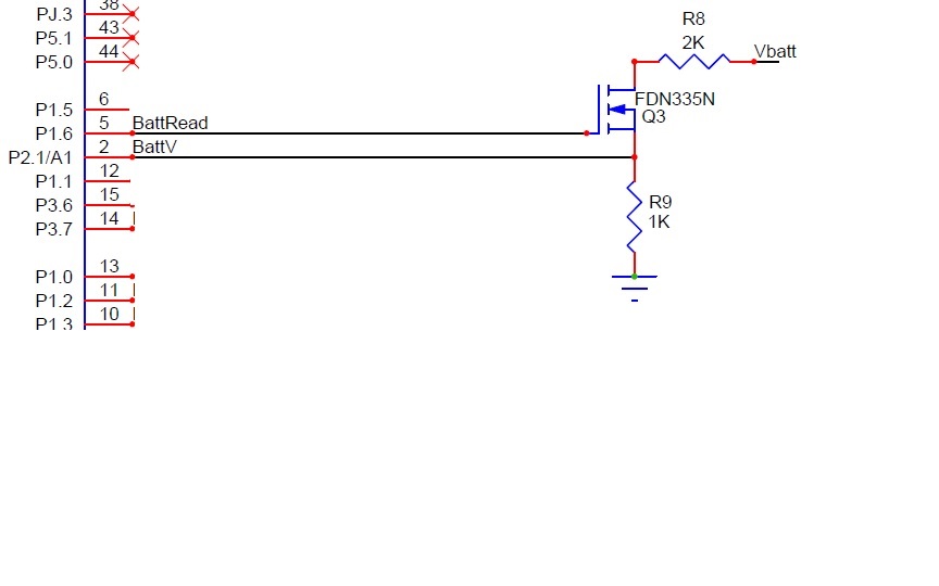
    Finally, if you are worried about the wasted power, then you can do something like the schematic image shown below. 

    Enable the transistor by setting BattRead high for about 1ms, then read BattV on the ADC input.

    Note that you want the ADC input to normally be pulled low. In the example below, when the transistor is off, R9 is a 1Kohm pull-down. If the ADC input was 'above' the transistor, the input would normally be pulled high to Vbatt when the transistor is turned off. If Vbatt was 9v, the ADC would see a 9v input. The uC has input protection diodes that prevent any inputs from exceeding Vdd or Gnd - so the diode would turn on and create a leakage path from Vbatt, through the voltage divider resistors, through diode in the uC and to Vdd. Basically, use the design shown below...

    Let me know if that makes sense and helps at all.

    - Chad C.