

In my last post, I discussed two important characteristics of delta-sigma analog-to-digital converters (ADCs) that simplify the design of your anti-aliasing filter: an oversampling architecture and a supplemental digital decimation filter. The oversampling architecture places the Nyquist frequency further away from your signal bandwidth of interest, while the digital decimation filter attenuates most of the unwanted out-of-band signals. When combined, they allow for a more relaxed anti-aliasing filter response, which you can achieve with only a few discrete components.
Figure 1. Keep those aliases back with a proper anti-aliasing filter
We know that using anti-aliasing filters is beneficial in precision ADC applications, but designing the right anti-aliasing filter is just as important – if you’re not careful, you can introduce unwanted errors into your system just as easily as you can remove them. Consider these three general guidelines when designing the anti-aliasing filter for your application.
- Choose your filter cutoff frequency
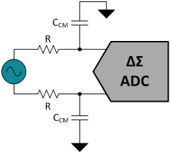
The simplest anti-aliasing filter is a single-pole, low-pass filter using a series resistor (R) and a common-mode capacitor (CCM), as shown in Figure 2. The first step in designing this filter is to select the desired cutoff frequency, fC. At fC, the filter’s response rolls-off to -3dB and continues to decrease at -20dB/decade in the frequency domain.
Choose a cutoff frequency at least a decade less than the ADC modulator sampling frequency, fMOD, in order to knock down the out-of-band noise at those frequencies by a factor of 10 or more. For increased attenuation, reduce the cutoff frequency further by increasing the values of R and CCM. Remember from my last post, your digital decimation filter is there to help too, so it’s not necessary to set your anti-aliasing filter cutoff immediately after your signal bandwidth of interest.
Equation 1 calculates the -3dB cutoff frequency for a single-pole, low-pass filter:
![]()

Figure 2. Single-pole, low-pass filter at the ADC inputs
Occasionally, a single-pole, low-pass filter may not be enough. Some applications, like vibration sensing, may use less oversampling to analyze signals over a wider bandwidth. This puts the passband of the digital decimation filter closer to fMOD and gives the anti-aliasing filter less room to roll-off. In these instances, you can add a second or third pole with additional RC pairs to achieve an even sharper filter response.
Figure 3 illustrates the response of a single-pole and a double-pole filter designed for an ADC, sampling the inputs at fMOD = 1MHz. The double-pole filter allows the flat passband to extend out to about 20kHz and still achieve -60dB of attenuation at 1MHz.
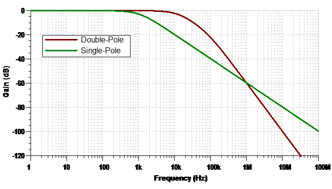
Figure 3. Frequency response of a single-pole and double-pole low-pass filter
2. Consider differential vs. common-mode filters
Many ADCs convert the differential voltage between two independent inputs (i.e. INP and INN), so designers often include common-mode filters on each input to maintain system common-mode rejection (CMR). However, component tolerances will introduce mismatch between any two filters and degrade CMR across frequency as they filter common signals differently. This produces a differential signal error through what is known as common-mode-to-differential conversion.
Equation 2 calculates the CMR of your common-mode anti-aliasing filters at a given frequency, f, using the resistor tolerance, RTOL, and the capacitor tolerance, CTOL:

For applications that require high CMR, consider adding a differential filter to supplement the two common-mode filters as shown in Figure 4. Set the differential cutoff to be one decade less than the common-mode cutoff by increasing the differential capacitor, CDIFF, by a factor of 10 over CCM. This will help mitigate errors introduced by common-mode component mismatch and create a sharper overall filter response. Equation 3 calculates the cutoff frequency for a differential low-pass filter. Notice the extra factor of 2 in the denominator.
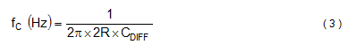
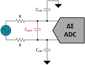
Figure 4. Common-mode filters with the addition of a differential filter
3. Select appropriate component values
Adding resistors to the signal path will introduce unwanted noise and errors in the measurement, so it is important to keep them reasonably small whenever possible.
Resistor noise – also known as Johnson or thermal noise – can be modeled as a voltage source in series with your ideally “noiseless” resistor. In general, you don’t want the resistor thermal noise to dominate the signal chain, so it is important to keep it below the noise floor of your ADC. Equation 4 calculates the noise density, vn, of resistor thermal noise:
![]()
where k = Boltzmann’s constant (1.38E-23 J/K) and T is the temperature in degrees Kelvin.
Series resistors also introduce a small offset voltage in the presence of input bias currents. While you may be able to calibrate this later, limit the size of your resistors as much as possible, especially when bias currents are expected to be large.
Unlike the filter resistors, the higher the capacitance you can use, the better. The reasoning behind this has to do with how ADCs sample the inputs.
The inputs of a delta-sigma ADC without an integrated buffer are connected directly to the switched-capacitor sampling structure of the ADC modulator. This sampling structure is comprised of a network of switches and sampling capacitors on the order of 10pF or 20pF. Figure 5 is a simplified example.

Figure 5. Simplified switched-capacitor sampling structure in an ADC
The switched-capacitor circuit places a transient load on the external circuitry during sampling. The filter capacitors help attenuate the sampling charge injection from the modulator and provide some of the instantaneous current needed to charge the sampling capacitor, CSAMPLE. The larger the filter capacitors, the more charge that will be available. Use NP0/C0G type ceramic capacitors because of their high Q-factor, low-temperature coefficient, and stable electrical characteristics. Larger capacitance values may also improve AC specifications like total harmonic distortion (THD), but keep in mind that this increases the filter’s RC time constant and requires a longer settling time.
I hope these three guidelines have prepared you to go about designing your next anti-aliasing filter. More importantly, I also hope that this blog series has taught you how aliasing occurs in data-acquisition systems and where delta-sigma ADCs hold an advantage over other ADC architectures. If there are other points that I did not cover, feel free to leave a question or comment below!
Additional resources
- Check out other posts by my colleagues with design tips and other delta-sigma ADC basics, including one I wrote on aliasing in ADCs and the advantages of the delta-sigma architecture.
- Find more than 100 data converter technical resources in our Data Converter Learning Center.
