Part 4 of this series discussed the issues and requirements involved in the design of a 2-wire sensor transmitter that accepts inputs from an externally powered sensor/source. In this installment, I’ll expand on the concepts presented in that post and discuss the design requirements of creating an input-isolated 2-wire transmitter as described in ANSI/ISA-50.1-1982.
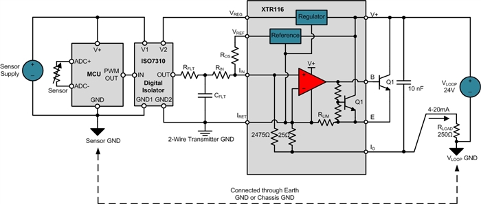
Figure 1 displays the 2-wire transmitter designed in part 4 that accepts inputs from an externally powered microcontroller (MCU) and sensor. In Figure 1, the local VREG circuit of the XTR116 only powers the V2/GND2 side of the ISO7310, while the sensor and MCU are powered from an external source.
As I described in part 4, externally powered input sources must be isolated from the input of the XTR116 to prevent the ground-loop issues I covered in part 2.
Figure 1: Isolating an externally powered MCU from the 2-wire transmitter with the ISO7310 digital isolator
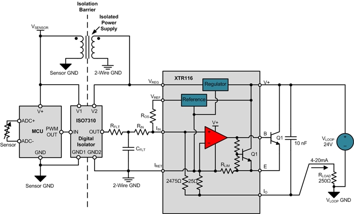
In an input-isolated 2-wire sensor transmitter, the sensor power and output signal are also fully isolated from the loop-powered circuitry; however, the isolated sensor power source is generated from the VLOOP or VREG voltage, as shown in Figure 2.
The isolated power supply, digital isolator and XTR must not consume more than 4mA of current, or the loop will not be able to regulate the output current down to the 4mA zero-scale level.
Figure 2: Simplified input-isolated 2-wire sensor transmitter
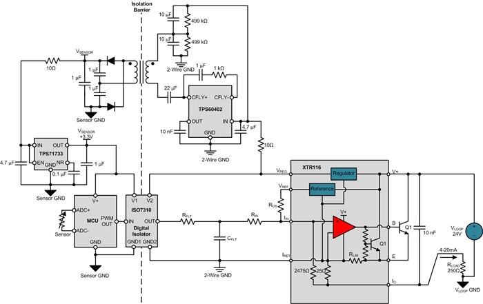
The design of the isolated power supply for the sensor circuitry is beyond the scope of this blog series, but is commonly accomplished with the use of push-pull or half-bridge forward-switching power-supply topologies. Figure 3 displays an unregulated, isolated half-bridge power supply using the TPS60402, followed by the TPS71733 low-noise low-dropout regulator (LDO). This circuit was designed specifically for 2-wire 4-20mA sensor transmitters and is featured in TI Designs reference design TIDA00167 (TIDU414). The TI Designs reference document explains the selection of the circuit’s passive components along with the requirements for the magnetics in the design.
Figure 3: Isolated power-supply solution for input-isolated 2-wire sensor transmitters
The isolated power-supply solution can be combined with the rest of the transmitter circuitry to form the example input-isolated 2-wire 4-20mA sensor transmitter shown in Figure 4.
Figure 4: Input-sensor-isolated 2-wire transmitter
Input-isolated 2-wire sensor transmitter designs require a low-power isolated power supply and a low-power method to isolate the sensor data. In Figure 4, the isolated power supply was created with an unregulated half-bridge switching converter. The sensor data was digitized and converted to a pulse-width modulated (PWM) signal, which was passed over the isolation barrier with a digital isolator. See TIDA00189 for a different implementation of an input-isolated 2-wire sensor transmitter.
Additional resources:
- View related TI Designs reference designs for 2-wire transmitters:
- http://www.ti.com/tool/TIPD126.
- http://www.ti.com/tool/TIPD158.
- http://www.ti.com/tool/TIDA-00189.
- Read 3-wire blog posts from my colleague Kevin Duke:
- See an overview of analog outputs and architectures.
- Read about the evolution of 3-wire analog outputs.
- See all the posts in our 2-wire transmitters series.
- Find commonly used analog design formulas in a new pocket reference put together by TI analog signal chain experts Art Kay and Tim Green.


