

Medical ultrasound is a noninvasive method of imaging the body’s internal structures (like organs) by transmitting high-frequency waves and measuring the reflections that occur at various boundaries within, such as between bone and muscle. There are different types of ultrasound, such as B-mode, F-mode (also known as pulsed-waveform) and continuous waveform Doppler (CW Doppler). Each has benefits and drawbacks, including what can be imaged and penetration depth.
In this post, I’ll be taking a closer look at CW Doppler and how a high-accuracy signal chain enables accurate measurement of blood flow deep within the body.
Figure 1 shows the concept of using CW Doppler to measure the rate of blood flow in a vein.
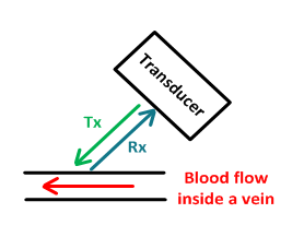
Figure 1: CW Doppler measurement of blood flow
In CW Doppler, half of the transducer array (transmitter/receiver array) continuously transmits a sine wave (denoted by Tx), which the blood cells flowing within a vein then reflect, or receive (denoted by Rx). The reflected signal has a different frequency than the transmitted effect, due to the velocity of the blood (this is known as the Doppler effect). The received signal is fed through a mixer and low-noise summer to demodulate the I and Q signals (the real and imaginary portions of the signal), which when simultaneously measured determine the phase change between the Tx and Rx signals. This phase change is used to calculate the velocity of the blood within the target vein.
Figure 2 shows a block diagram of the Rx portion of the CW Doppler signal chain.

Figure 2: Block diagram of a CW Doppler signal-conditioning circuit (replicated for both I and Q measurement)
Figure 2 highlights the Rx signal chain because of the difficulty in measuring the received signal. While the Tx waveform can be anywhere from 1 to 15MHz with an amplitude of ±2.5V to ±100V, the received signal can be as low as ±10µV and as large as ±500mV. The range of Rx depends on the speed of the blood flow, the angle of the transducer relative to the direction of blood flow and the depth of the vein.
A high-precision analog-to-digital converter (ADC) accurately measures the reflected signal. For CW Doppler, a successive approximation register (SAR) ADC is preferable because it provides the raw conversion (no digital filtering) and has low latency and excellent AC performance. Depending on the desired accuracy and how deep the target veins are expected to be, a high resolution ADC is necessary. The ADS8900B family is an excellent choice because it meets the required performance and throughput, and offers the wide input range necessary for measuring the dynamic signals created by CW Doppler. You can easily design a simultaneous sampling system using two ADS8900B devices to measure the I and Q channels. Table 1 shows several of the key specifications for the ADS8900B family.

Table 1: ADS8900B family key specifications
While the high performance of the ADS8900B family alone enables it to accurately measure blood flow, another advantage that it offers is an internal reference buffer. The voltage reference circuit is a crucial aspect of the signal chain, as it provides a point of reference for the ADC. Any deviation in the voltage reference can result in an inaccurate conversion. Figure 3 shows an external vs. internal reference buffer configuration.

Figure 3: External vs. internal voltage reference buffer
During a signal conversion cycle, the ADC will draw current from the reference to charge a switched capacitor, and compare this voltage to the voltage of the input signal. While drawing current, this reference voltage is prone to voltage droop on the output if not supplied with sufficient current (again, possibly resulting in inaccurate conversion). The voltage reference buffer supplies adequate current to the ADC so as to avoid a voltage droop. Integrating the voltage reference buffer into the ADC not only reduces the overall system size – which is critical for portable or high-channel-count CW Doppler systems – but the buffer is designed specifically for the ADC, further improving overall system performance. The integrated buffer enables the use of a single voltage reference with multiple ADCs, further reducing board space and cost for multichannel systems.
I hope that I have explained how the high precision and integration of the ADS8900B enables CW Doppler ultrasound systems. If you enjoyed this post, be sure to sign in and subscribe to Precision Hub to get similar posts delivered right to your inbox.
Additional resources
- Explore TI’s selection of precision ADCs.
- Check out the CW Doppler reference design, “High-Resolution, High-SNR True Raw Data Conversion Reference Design for Ultrasound CW Doppler.”
- Learn more about designing with the ADC8900B in these blog posts:
-

Eric Fletcher
-
Cancel
-
Vote Up
0
Vote Down
-
-
Sign in to reply
-
More
-
Cancel
Comment-

Eric Fletcher
-
Cancel
-
Vote Up
0
Vote Down
-
-
Sign in to reply
-
More
-
Cancel
Children