

Winter is my favorite time to work on hobby projects in Texas. My garden is filled with easy-to-maintain winter or cover crops, and it’s cool enough to work outside without overheating.
While working on a recent project, I had to re-route some electronic wiring away from an off-road vehicle’s alternator because capacitive coupling was introducing noise from the alternator into the wiring. The project reminded me of a common situation people face when routing signals adjacent to each other over wiring, ribbon cables or board-to-board connectors.
Any two wires routed adjacent to each other will develop capacitance between them, just as any other conductors separated by an insulator. Depending on the wire gauge and insulator material used, most standard ribbon cables and wires have a capacitance in the range of 10 – 50 pF/ft between wires as shown in Figure 1 below.
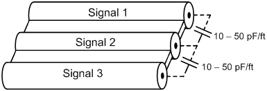
Figure 1. Capacitance between adjacent wires in a ribbon cable
Capacitance between the two signal lines can cause signal delays, noise coupling or transient voltages as the signals interfere with each other.
Figure 2 shows an example where cable capacitance caused large transient voltages in a common 2-wire open-drain communication bus. The image on the right is the zoomed-in version of the START command and the first few clock pulses of the image on the left.
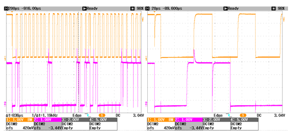
Figure 2. Capacitive coupling from ribbon cable capacitance
The results from Figure 2 occurred when I routed the two communication signals adjacent to each other over three feet of cable. This resulted in over 50 pF of capacitance between the two signals.
Due to the capacitance, when a transition occurred on one signal, it caused a voltage transient on the other signal. This happened because the cable capacitance required transient current to flow between the signals when one of the signal levels changed.
The magnitude of the transient voltage seen on the static signal is dependent on the inductance of the cable and the ability of the signal driver to supply the required transient current. In this case, the communication was not successful because the transient voltages caused by the coupling were large enough to surpass the logic level threshold causing data corruption.
Placing one or more GND wire(s) between signals will reduce the capacitance between them, as shown in Figure 3. This method reduces the signal-to-signal capacitance but results in capacitance to GND from each signal. The capacitance to GND will cause signal delays and rounding of the digital edges but will typically not cause communication failures as long as the effects are not too severe.
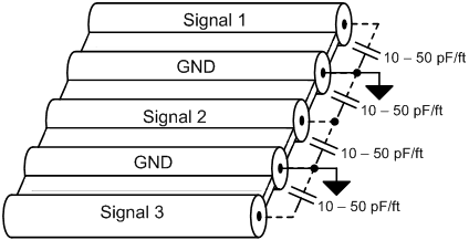
Figure 3. Separating signals with GND
Figure 4 displays the communication signal results after I modified it to include two GND signals between the signal wires. The modification reduced the signal-to-signal capacitance to around 10 pF. As a result, the transient voltages were greatly reduced and the communication was successful.
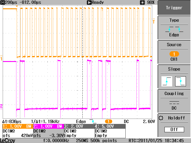
Figure 4. Successful communication with reduced capacitance
In summary, beware of the effects of stray capacitive coupling when designing your cable, wiring or PCB routing designs. In applications requiring longer cables, select a lower capacitance cable and always route one or more ac GND signal(s) between signals that may couple into each other.
If you’d like to dig into this topic a little deeper, here are some additional resources to check out:
- A Practical Guide to Cable Selection application note
- LVDS: The Ribbon Connection Analog Application Journal article
- Performance of LVDS with Different Cables application report
- Suggestions for High-Speed Differential Connections application report
- PCB Design Guidelines for Reduced EMI application report
- Learn about TI’s entire portfolio of amplifier ICs and find other technical resources


