

As an applications engineer, I field a lot of questions from system designers on how to decipher datasheet specifications. Just when I think I understand how specifications are determined and how they translate to error in a design, I’ll get a TI E2E™ Support Forum post, phone call or e-mail from a customer that shows otherwise.
I actually got a question the other day about the conditions column of a data sheet. The OPA188 data sheet, for example, doesn’t list test conditions for the input offset voltage parameter (Figure 1). Therefore, the conditions listed at the top of the electrical characteristics table apply to the input offset voltage parameter. This is true for all parameters in a data sheet unless otherwise noted.
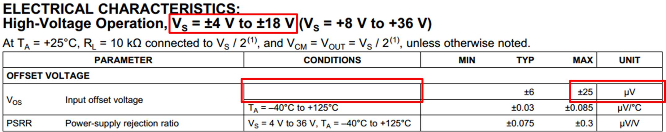
Figure 1. OPA188 datasheet
In this case, the specification is valid for the supply voltage range listed at the top of the electrical characteristics table. Changing the supply voltage will change the offset voltage per the power-supply rejection ratio (PSRR) parameter, but final test ensures the offset voltage will not exceed ±25µV across all supply voltages.
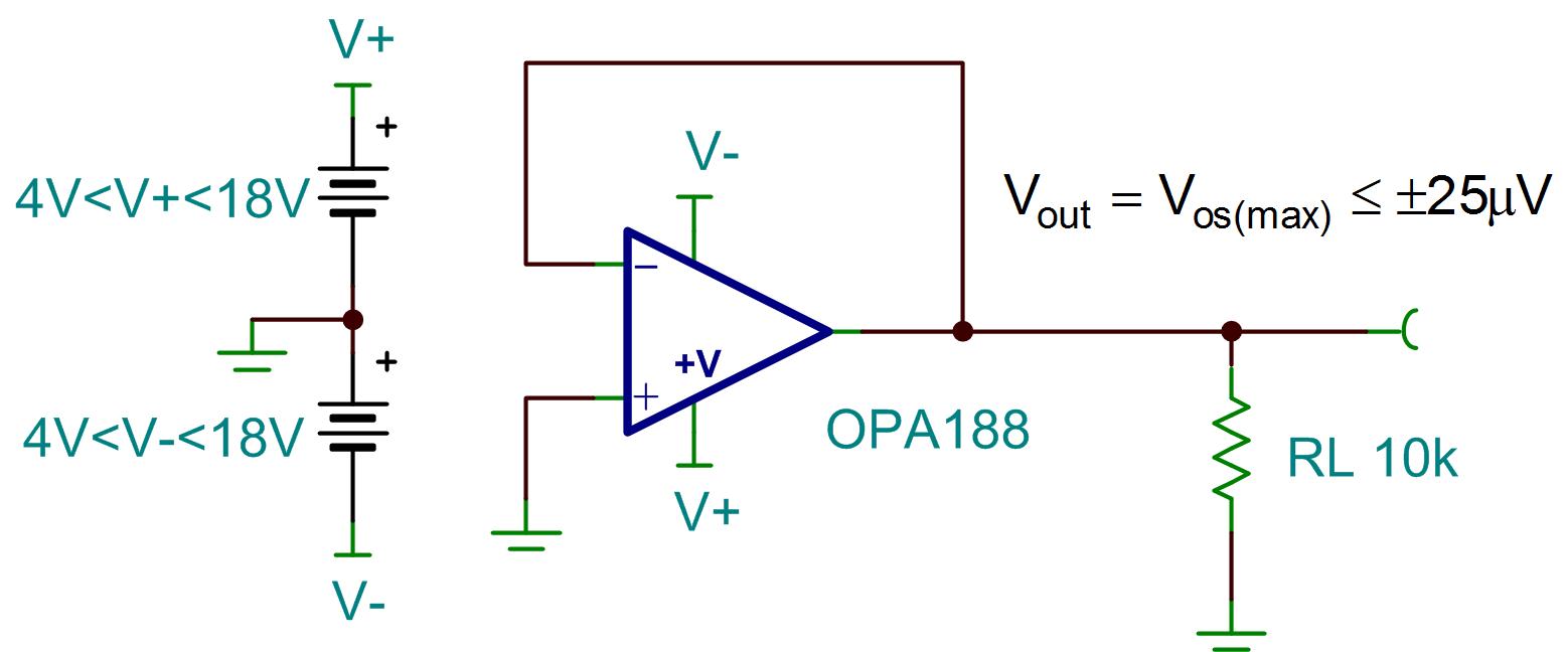
Figure 2. OPA188-Maximum offset voltage, ±4V<Vs<±18V
The input offset voltage of the OPA211, however, is valid only for the supply voltage test condition shown in Figure 3.

Figure 3. OPA211 datasheet
Figure 4 depicts the maximum input offset voltage for VS=±15V.

Figure 4. OPA211 maximum offset voltage, Vs=±15V
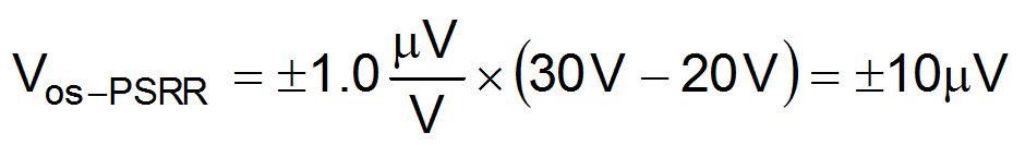
Changing the supply voltage of the OPA211 from ±15V to ±10V introduces additional offset voltage due to the device’s PSRR specification (±1µV/V). Equation 1 shows how to calculate the additional offset voltage due to changing the supply voltage.
Equation 1. Maximum additional offset voltage due to PSRR
Adding the offset voltage from PSRR directly to the initial input offset voltage yields the worst-case error. Combining the errors in a root-sum-square (RSS) fashion yields a more probable error term. Figure 5 depicts the maximum offset voltage of the OPA211 when Vs=±10V.

Figure 5. OPA211 offset voltage, Vs=±10V
While the additional offset voltage may seem small (0.4µV to 10µV), remember that offset voltage is referred to the input. If the amplifier is in a gain of 100V/V, the output of the OPA211 could vary as much as ±1mV by simply changing the power supply voltage.
In summary, changing the supply voltage of any amplifier will shift the offset voltage according to the PSRR specification. Depending on the test conditions, however, the offset voltage specification may already account for changes in the power supply. If not, you may get more error than you expect!
Next time you have too much error at the output of an amplifier, be sure to check the test conditions of the specifications in the data sheet!
